Table of Contents
Advertisement
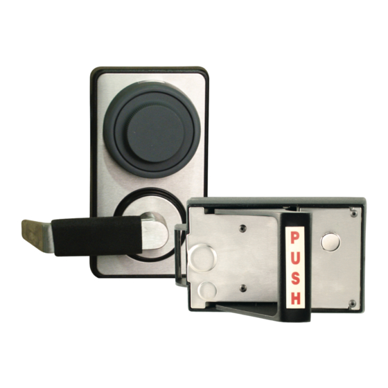
LKM7000
Increased Safety, Increased Security, Increased Functionality.
INSTALLATION INSTRUCTIONS
In A Single Motion, We'll Change The Way
You Think About Security.
90 minute fire rating alone or
with Kaba Mas X09.
Not rated when used with a
National Stock Number 5340-01-501-2828 US Patent #7,007,524,B2
S&G 2740 lock.
1
7000INST
Copyright Lockmasters, Inc. 5/25/11
Advertisement
Table of Contents

Subscribe to Our Youtube Channel
Related Manuals for LockMasters LockOne LKM7000


Summary of Contents for LockMasters LockOne LKM7000
-
Page 1: Installation Instructions
LKM7000 Increased Safety, Increased Security, Increased Functionality. INSTALLATION INSTRUCTIONS In A Single Motion, We’ll Change The Way You Think About Security. 90 minute fire rating alone or with Kaba Mas X09. Not rated when used with a National Stock Number 5340-01-501-2828 US Patent #7,007,524,B2 S&G 2740 lock. - Page 2 LKM7000 EXPLODED VIEW LKM7000 Inside Base Plate Exploded View LOCKBODY AND PARTS Component Part No. Inside Base Plate Complete w/ Screws & Hardware 700013WBA Internal Access Control 700016 Handle Tube 700013S01 Extended Spindle Kit 700013S01EXT Complete Wiring Harness 700013S45 Yoke...
- Page 3 LKM7000 Front Plate Exploded View Component Part No. Handle Screw 700012S13 Lock Washer for Handle Screw 700012S18 Intermediate Gear 700012S14 Hub Handle Half Gear 700012S01 Handle return Spring 700012S12 Outside Lever Handle 700012S11 Neoprene Handle Grip 7000HANDGRP Complete Front Plate Assembly 700012WBA Not all items are field retro-fittable.
- Page 4 Record the Lock’s Serial Number prior to installation: WARNING - Must read before installation IT IS IMPERATIVE THAT THE DOOR REMAIN OPEN DURING INSTALLATION OF THE LKM7000. If the door closes while the back cover is removed, the relockers will trigger resulting in a lockout. Important Information All seals and gaskets must be applied to the door frame PRIOR to installing a LockOne Series Lock.
- Page 5 Optional Products STAND-OFF KIT for the LockOne Series Lock We strongly recommend using a Stand-Off Kit, which prevents a hollow metal door from compressing during installation of a LockOne Series Lock. Stand-Off Kits are sold separately and available for 1 3/4” and 2” doors. PART NUMBERS: 1 3/4”...
- Page 6 LKM7000 Strikes Strike 1 Strike 2 LKM01S LKM02S Strike 9 Strike 3 Strike No. 9 LKM09S LKM03S 7000INST Copyright Lockmasters, Inc. 5/25/11...
- Page 7 M. Liquid Thread Locker N. Change Key Hole Plug O. Filler Blocks (2) Templates Q. Installation Instructions R. Operating Instructions LKM7000 Installation - Tools Needed Drill Hammer 1/8” Drill Bit 1 5/8” Wood Cutting Bit Wire Cutters or Strippers Small Pocket Screwdriver 3/16”...
- Page 8 LKM7000 Strike Installation For this application the LKM7000 is installed on a single hollow metal door with a #2 strike, however the instructions apply to any strike. Please note Lockmasters has stainless steel strikes exclusively for the LKM7000 family of locks.
- Page 9 LKM7000 Installation Step 4 – Position the Inside Base Plate Template Close the door and align the Inside Base Plate template over the strike and level with the indicated horizontal level line on the template. Make sure to keep equal clearance around the strike.
- Page 10 LKM7000 Installation Position the Front Plate Template continued Step 5D – Once the high side of a beveled edge door is established. Loosen the combination square and position the rule to the vertical plumb line on the inside base plate template and tighten the combination square. (Figure 3).
- Page 11 - Punch only if you are utilizing one or more of the following: 12 or 24v dc Access Control input, Monitoring the position of the Combination Lock Bolt, and Monitoring the position of the LKM7000 Dead Bolt/Request to Exit (REX). Potentially (12) holes. Step 7B – Re-tape the template above the punched holes for easy reference. Label...
- Page 12 LKM7000 Installation Step 8 – Drill Pilot Holes Step 8A - We recommend using a 1/8” drill bit to pilot drill all center punched holes. 8a- Drilling pilot holes on both sides of the door. Step 9 – Drill the Inside Base Plate side of the door Step 9A - Drill the (1) A, clutch hole –...
- Page 13 LKM7000 Installation Step 11 – Prep all drilled holes Step 11A - Use the debur stone to debur all drilled holes. Step 11B - Pre-thread all (4) C Inside Base Plate attaching holes – using one of the Phillips head thread forming screws (F). A #2 square drive bit works well with the screws.
- Page 14 LKM7000 Installation IF STANDOFF KIT IS BEING USED - INSTALL NOW Stand-offs are used to prevent a hollow metal door from compressing during installation. The kit is applied to the backside of the Front Plate. Take the (6) threaded set screws that come in the Stand-off kit and thread them into the backside of Front Plate.
- Page 15 DOOR WARNING – It is imperative that the door remains open during installation of the LKM7000. If the door closes and latches while the back cover is removed the relockers will trigger into a lock-out. Step 15 – Measure the Spindle Tube Step 15A –...
- Page 16 LKM7000 Installation Step 16 – Remove & Cut Spindle Tube to Correct Length Step 16A – Use your snap ring pliers to remove the internal spindle tube retaining ring. Step 16B – Remove the spindle tube from the Inside Base Plate by pulling the spindle tube through the Inside Base Plate then remove the remaining external spindle tube retaining ring.
- Page 17 LKM7000 Installation Step 17 – Use of Filler Blocks Step 17A – Insert the applicable filler block into the inside base plate before installation. Option 1 – If you are not utilizing Access Control or monitoring the bolt sensors, push the wire into the inside base plate.
- Page 18 LKM7000 Installation Step 18 – Secure the Inside Base Plate to the door IF HARDPLATE IS BEING USED - INSTALL NOW Align the hard plate to the backside of Inside Base Plate and secure with double-sided tape. Secure by inserting (2) of the metal thread forming screws (F) into the base plate holes (C) to hold the hard plate in position while securing the Inside Base Plate to the door (See Figure 6).
- Page 19 Step 19 – Solenoid Activation ACCESS CONTROL Step 19A – Access Control Integration The LKM7000 is shipped with an internal solenoid requiring 24v dc to retract the solenoid pin. OPTIONAL - In order to use a 12v dc access control unit you’ll need to peel back the blue heat shrink material away and cut the RESISTOR out of the circuit.
- Page 20 The combination lock bolt sensor monitors the extension and retraction of the combination lock bolt. The LKM7000 Deadbolt Sensor/REX can be used to monitor the LKM7000 Deadbolt . This can also be used as a Request to Exit switch to shunt an alarm system. (See Figure 9 - Wire Diagram)
- Page 21 Step 22a - Remove Warning Label Remove the internal warning label in the Inside Base Plate. Step 22b - When integrating a combination lock package with the LKM7000 follow the lock manufacturer’s instructions to install properly. 22a - Remove warning label from IBP.
- Page 22 LKM7000 Installation Step 24 - Strike Adjustment Step 24A – Close the door to ensure proper function. Make sure that no part of the Inside Base Plate is rubbing the strike. Now is the time to make adjustments to the strike if necessary.
- Page 23 LKM7000 Installation Final Step - Test the Lock After completing the installation, please read the enclosed operation instructions and test the functionality of the combination lock, access control, LKM7000 and the door. Test the LKM7000 7000INST Copyright Lockmasters, Inc. 5/25/11...
- Page 24 Limited Liability Product Warranty Information Lockmasters, Inc. warrants to the original retail purchaser for a period of one (1) year from the purchase date of the product that the product shall be free of defects in the materials and workmanship, provided there is compliance with all installation, operating and maintenance instructions provided by Lockmasters, Inc.
Need help?
Do you have a question about the LockOne LKM7000 and is the answer not in the manual?
Questions and answers