Advertisement
Quick Links
I N S T A L L A T I O N
INSTRUCTIONS
1. Determine the vertical centerline of the door lock face and
the horizontal centerline of the latch.
IMPORTANT: When determining the horizontal centerline
observe the following:
FOR MORTISE LOCKS: Align the angled ramps of the lip
bracket with the deadlock trigger of the mortise latch.
FOR CYLINDRICAL LOCKS: Align the center of the latch
with the center of the strike opening.**
2. Transfer both the horizontal and vertical centerlines to the
door frame.**
3. Prepare the door frame for cutting as per the
appropriate drawing.
F4104 Aluminum Frames 1-1/2 Insert Depth
A
1-1/4"
1.250
31.75
B
4-7/8"
4.875
123.83
C
3-3/8"
3.375
85.73
D
29/32
0.906
23.02
3/8"
0.375
9.53
E
F
1/8"
0.125
3.18
G 1-11/16"
1.688
42.86
Vertical Centre Line of Door
X
Lock and Mounting Face Plate**
5/32"
0.156
3.97
R
K
4-1/8"
4.125
104.78
M 12-24
N/A
N/A
NOTE: Specifications subject to change without notice.
* Dimension F is measured from face of mounting tab to face of frame.
** Dimension X on the drawing is determined by the vertical centerline of the door. If the latch incorporates a deadlocking pin additional steps will be
necessary to ensure proper operation of the deadlocking pin. Measure the thickness of the deadlocking pin and add this thickness to Dimension X to
relocate the vertical centerline to an appropriate distance on the frame.
ISF4
www.rutherfordcontrols.com • Phone: 1.800.265.6630 • fax: 1.800.482.9795 • e-mail: sales@rutherfordcontrols.com
4. If required, install the optional "no weld" mounting
brackets as per the instructions on page 2.
5. Connect the incoming wiring from the power supply to
the terminal screws on the strike insert. RCI door strikes
are not polarity sensitive although be certain to observe
proper polarity if a suppression diode is required for access
control applications. To meet BHMA A156.31 install the
MOV provided across the red and black power wires.
6. Install the door strike in the door frame using the screws
provided.
C
C
© 2015 RutheRFoRd CoNtRolS INt'l | A doRMA GRouP CoMPANy
In or Out... we make it Easy!
F4114 Hollow Metal Frames 1-1/2 Insert Depth
1 1/4"
1.250
31.75
A
B
4 7/8"
4.875
123.83
C 3-3/8"
3.375
85.73
D
29/32
0.906
23.02
3/8"
0.375
9.53
E
F
1/8"
0.125
3.18
G 1-11/16"
1.688
42.86
Vertical Centre Line of Door
X
Lock and Mounting Face Plate**
K 4-1/8"
4.125
104.78
M 12-24
N/A
N/A
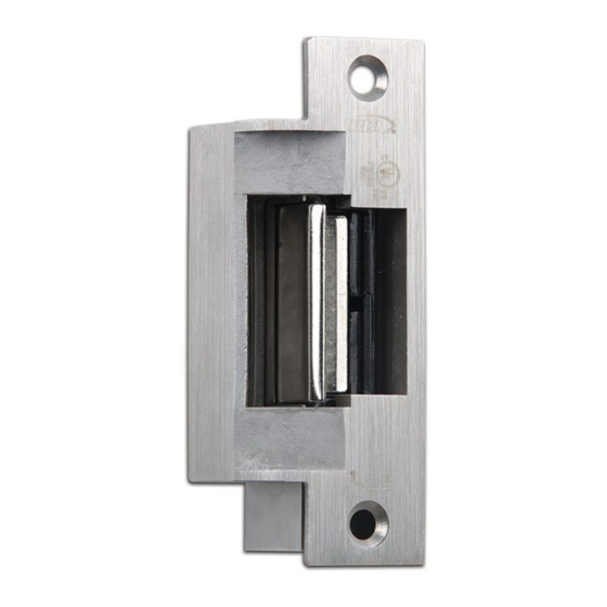
F4 series
electric strikes
C
C
PCN14079
R06/15GR
®
Advertisement

Related Manuals for Dorma RCI 4 Series


Summary of Contents for Dorma RCI 4 Series
- Page 1 Measure the thickness of the deadlocking pin and add this thickness to Dimension X to relocate the vertical centerline to an appropriate distance on the frame. ISF4 PCN14079 © 2015 RutheRFoRd CoNtRolS INt’l | A doRMA GRouP CoMPANy R06/15GR www.rutherfordcontrols.com • Phone: 1.800.265.6630 • fax: 1.800.482.9795 • e-mail: sales@rutherfordcontrols.com...
- Page 2 4. Make final electrical connections per wiring instructions and mount strike to the tabs with the 12-24 x 3/8” machine screws. Frame © 2015 RutheRFoRd CoNtRolS INt’l | A doRMA GRouP CoMPANy www.rutherfordcontrols.com • Phone: 1.800.265.6630 • fax: 1.800.482.9795 • e-mail: sales@rutherfordcontrols.com...
Need help?
Do you have a question about the RCI 4 Series and is the answer not in the manual?
Questions and answers