
Related Manuals for Quickplay PRO ALU MATCH


Summary of Contents for Quickplay PRO ALU MATCH
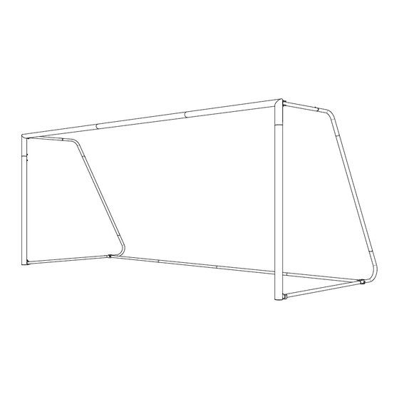
- Page 1 21 x 7FT PRO ALU MATCH GOAL QUICKPLAY ® @quickplay_sport / @quickplay_soccer www.quickplaysport.com / www.quickplaysport.us Customer service: support@quickplaysport.com...
-
Page 2: Parts List
PARTS LIST PARTS LIST AL21-9 AL21-1 AL21-10 Top C onnector (2x) Crossbar Left (1x) Top S ide Frame (2x) AL21-11 AL21-8 Crossbar Right (1x) Diagonal Side Frame (2x) AL21-2 Upright (2x) AL21-6 AL21-7 AL21-3 Side Frame (2x) Bottom Connector (2x) Crossbar Section 2 (1x) AL21-4 F/F Basebar (2x) - Page 3 HANDY EXTRAS HANDY EXTRAS PARTS LIST Wrench Allen Key Ratchet with Sockets WARNING INFORMATION 1. Read through the instruction manual thoroughly before assembling the goal. 2. Check parts for any defects prior to the assembly of the goal. 3. Only use the goal on a flat surface. 4.
-
Page 4: Product Assembly
PRODUCT ASSEMBLY HANDY EXTRAS PARTS LIST AL21-1 Figure. 1 ALU-1 AL21-3 STEP 1 - Crossbar (Figure 1) ALU-2 Layout the crossbar parts (AL21-1, AL21-11 & AL18-3) and connector (ALU-1 x2). Slide 2x Bolts parts (A1) into parts (AL21-1) & 2x Bolts parts A1 into parts (AL21-3) ensuring they are between the holes. - Page 5 Figure. 3 AL21-11 STEP 3 - Attach Crossbar to uprights (Figure 3) Slide 4x M10x25 bolts (A1) into the corner section of the end of the crossbar right (AL21-11). Slide 4x M10x25 bolts (A1) into the (AL21-2) upright. Part 1: Attach one connector (ALU-1) to the Crossbar right (AL21-11).
- Page 6 Figure. 5 STEP 5 - Fixing Bottom brackets to uprights (Figure 5) Slide 1x Bolt (A1) into the base of both uprights (AL21-2) Place the bottom brackets (ALU-6) onto the Uprights and ensure the (A1) bolt slots through the required hole on the bottom bracket.
- Page 7 STEP 7 - Fix Basebar joints to Figure. 7 side frames (Figure 7) Place the Basebar joint (ALU-7) over the unsecured Bolts (B3) Secure each Basebar joint to the bottom side frame (AL21-6) with an lock nut (B2) ALU-7 AL21-6 AL21-7 AL21-1 SP-1...
- Page 8 STEP 9 - Side frames (Figure 9) Slot Basebar pieces (AL21-4, AL21-5 & AL21-5a) together. The parts will need to be attached using the spring clips, to do this push on the spring clip and push the tubes together at the same time. (See diagram below) Figure.
- Page 9 STEP 12 - Attaching the Net Figure. 12a Place the net over the frame, denote that ‘Top Corner’ tabs as per (Figure 12a). Attach net the to the frame using the net clips (NC-1). The push and twist technique is shown in the (Figure. 12b) Figure.
- Page 10 Secure the net along the Basebar, using the cable ties (CT-1), As per Figure. 12c, you may also wish to add cable ties Figure. 12c to the side bars which may add more tension to your goal Cable ties Place each Cable tie CT-1 three net sqaures apart...
- Page 11 Undo Cable ties connecting the net to the Basebar Undo securing pin from Basebar brackets, then remove Basebar. Fold Sidebars inwards 90 degrees towards the crossbar.
Need help?
Do you have a question about the PRO ALU MATCH and is the answer not in the manual?
Questions and answers