Table of Contents

Related Manuals for High-Flying HF-LPX70 Series


Summary of Contents for High-Flying HF-LPX70 Series
- Page 1 HF-LPX70 Series Wi-Fi&BLE User Manual HF-LPX70 Series Low Power Wi-Fi + BLE Module User Manual V2.7 HF-LPX70 series include the following modules: - 1 - Shanghai High-Flying Electronics Technology Co., Ltd(www.hi-flying.com)
- Page 2 HF-LPX70 Series Wi-Fi&BLE User Manual Overview of Characteristic Support Wi-Fi IEEE802.11b/g/n and BLE5.0 Wireless Standards Based on RISC SOC, 160MHz CPU, 276KB RAM, 2MB/8MB Flash Support UART Data Communication with Wi-Fi or BLE Support Wi-Fi STA/AP/AP+STA Mode ...
-
Page 3: Table Of Contents
HF-LPX70 Series Wi-Fi&BLE User Manual TABLE OF CONTENTS LIST OF FIGURES ..............................9 LIST OF TABLES ..............................11 HISTORY................................12 PRODUCT OVERVIEW ..........................13 1.1. General Description ..........................13 1.1.1 Key Application ..........................14 1.1.2 Device Paremeters ......................... 14 1.2. - Page 4 HF-LPX70 Series Wi-Fi&BLE User Manual 2.8. UART Frame Scheme ........................... 51 2.9. Encryption ............................. 51 2.10. Parameters Configuration ........................ 52 2.11. Firmware Update..........................52 2.12. SOCKB Function ..........................52 2.13. Multi-TCP Link Connection ......................53 2.14. Event Notification Function ......................53 2.15.
- Page 5 HF-LPX70 Series Wi-Fi&BLE User Manual 5.1. Configuration Mode ..........................69 5.1.1. Switch to Configuration Mode ......................69 5.1.2. Send AT Command in Transparent Transmission Mode ..............70 5.2. AT+Instruction Set Overview ....................... 70 5.2.1. Instruction Syntax Format ....................... 71 5.2.2.
- Page 6 HF-LPX70 Series Wi-Fi&BLE User Manual 5.2.6.10. AT+RECV: Receive Data from SOCKA at Command Mode ............83 5.2.6.11. AT+SOCKB: Set/Query SOCKB parameters. Setting is valid immediately ......... 83 5.2.6.12. AT+TCPDISB: Open/Close SOCKB TCP client link ..............84 5.2.6.13. AT+TCPTOB: Set/Query Operation SOCKB TCP timeout. Setting is valid after reset ....84 5.2.6.14.
- Page 7 HF-LPX70 Series Wi-Fi&BLE User Manual 5.2.11.1. AT+WMODE: Set/Query Wi-Fi work mode. Setting is valid after reset ........96 5.2.11.2. AT+MDCH: Set Wi-Fi Auto Switch Function. Setting is valid after reset ........97 5.2.11.3. AT+ASWD: Set/Query WiFi Configuration Password ..............97 5.2.11.4.
- Page 8 HF-LPX70 Series Wi-Fi&BLE User Manual C.3.SmartAPLink ............................111 C.4.SmartLink V8 ............................111 APPENDIX D: CONTACT INFORMATION ....................112 - 8 - Shanghai High-Flying Electronics Technology Co., Ltd(www.hi-flying.com)
-
Page 9: List Of Figures
HF-LPX70 Series Wi-Fi&BLE User Manual LIST OF FIGURES Figure 1. Block Diagram ............................ 13 Figure 2. HF-LPT270-1 Appearance ........................16 Figure 3. HF-LPT270-0 Appearance ........................16 Figure 4. HF-LPT270-2 Appearance ........................16 Figure 5. HF-LPT170-10 Appearance ........................ 16 Figure 6. - Page 10 HF-LPX70 Series Wi-Fi&BLE User Manual Figure 43. Transparent Transmission Mode Registration Package Function Example ........46 Figure 44. Transparent Transmission Mode Heartbeat Packet Function Transmission ........47 Figure 45. HTTP Mode Transmission ......................48 Figure 46. HTTP GET Request Example ......................49 Figure 47.
-
Page 11: List Of Tables
HF-LPX70 Series Wi-Fi&BLE User Manual LIST OF TABLES Table1. HF-LPX70 Series Module Technical Specifications ................14 Table2. HF-LPT270 Pins Definition ......................... 19 Table3. HF-LPT270-X-B/BR Pin defination ..................... 21 Table4. HF-LPT170 Pins Definition ......................... 22 Table5. HF-LPT271 V3 Pins Definition ......................23 Table6. -
Page 12: History
HF-LPX70 Series Wi-Fi&BLE User Manual HISTORY Ed. V1.0 06-09-2020 First Version. Ed. V1.1 06-10-2020 Update some error description Ed. V1.2 07-16-2020 Update 1MB and 2MB software difference. Ed. V1.3 08-24-2020 Add HF-LPT170, HF-LPB170, HF-LPB175 type. Ed. V1.4 09-16-2020 Delete 1MB version, and Add HF-LPT271 type. -
Page 13: Product Overview
1. PRODUCT OVERVIEW 1.1. General Description The HF-LPX70 series module is a fully self-contained small form-factor, single stream, 802.11b/g/n Wi-Fi + BLE module, which provide a wireless interface to any equipment with a Serial interface for data transfer. This module integrate MAC, baseband processor, RF transceiver with power amplifier in hardware and all Wi-Fi protocol and configuration functionality and networking stack, in embedded firmware to make a fully self-contained 802.11b/g/n Wi-Fi and BLE solution for a variety... -
Page 14: Key Application
HF-LPX70 Series Wi-Fi&BLE User Manual 1.1.1 Key Application ⚫ Remote equipment monitoring Asset tracking and telemetry ⚫ Security ⚫ ⚫ Industrial sensors and controls ⚫ Home automation ⚫ Medical devices 1.1.2 Device Paremeters Table1. HF-LPX70 Series Module Technical Specifications Class... -
Page 15: Hardware Introduction
Support SDK for application develop Parameters Network Protocol IPv4, TCP/UDP/HTTP/TLS 1.2 AT+instruction set. SmartBLELink BLE Config User Configuration SmartAPLink AP Config SmartLink Config 1.2. Hardware Introduction HF-LPX70 series Wi-Fi module appearance is as following. - 15 - Shanghai High-Flying Electronics Technology Co., Ltd(www.hi-flying.com) -
Page 16: Figure 2. Hf-Lpt270-1 Appearance
HF-LPX70 Series Wi-Fi&BLE User Manual Figure 2. HF-LPT270-1 Appearance Figure 3. HF-LPT270-0 Appearance Figure 4. HF-LPT270-2 Appearance Figure 5. HF-LPT170-10 Appearance - 16 - Shanghai High-Flying Electronics Technology Co., Ltd(www.hi-flying.com) -
Page 17: Figure 6. Hf-Lpt170-00 Appearance
HF-LPX70 Series Wi-Fi&BLE User Manual Figure 6. HF-LPT170-00 Appearance HF-LP271 exist two version V2 and V3, V2 will be suspended sooner. Figure 7. HF-LPT271 V3 Appearance Figure 8. HF-LPT271 V2 Appearance - 17 - Shanghai High-Flying Electronics Technology Co., Ltd(www.hi-flying.com) -
Page 18: Figure 9. Hf-Lpt271-0 Appearance
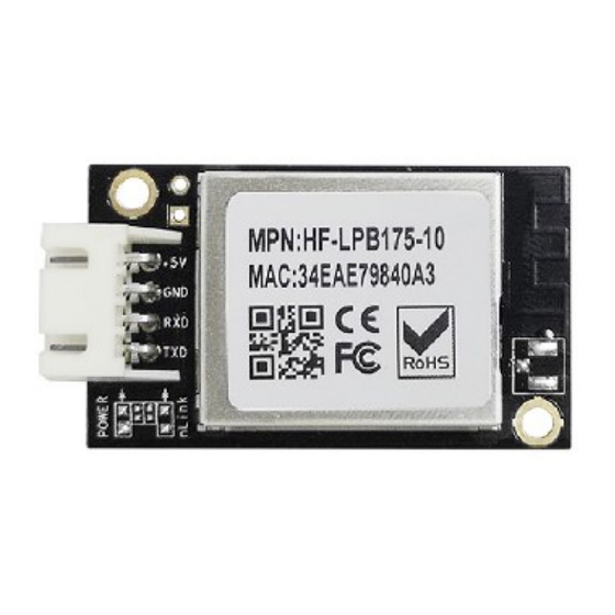
HF-LPX70 Series Wi-Fi&BLE User Manual Figure 9. HF-LPT271-0 Appearance Figure 10. HF-LPT272 Appearance Figure 11. HF-LPB170 Appearance Figure 12. HF-LPB175 Appearance - 18 - Shanghai High-Flying Electronics Technology Co., Ltd(www.hi-flying.com) -
Page 19: Hf-Lpt270 Pins Definition
HF-LPX70 Series Wi-Fi&BLE User Manual Figure 13. HF-LPT570 Appearance 1.2.1. HF-LPT270 Pins Definition Figure 14. HF-LPT270 Pins Map Table2. HF-LPT270 Pins Definition Describtion Net Name Signal Comments Type UART1_TX DEBUG_UART1_TX 3.3V TTL UART1 Debug Output GPIO17, SPI function UART1_RX DEBUG_UART1_RX 3.3V TTL UART1 Debug Input... -
Page 20: Figure 15. Hf-Lpt270-Pad Antenna Out
HF-LPX70 Series Wi-Fi&BLE User Manual Describtion Net Name Signal Comments Type leave it unconnected for user application Module Reset RESET I,PU “Low” effective reset input. There is RC reset circuit internally. No need of external RC reset circuit. 11 Module Boot Up nReady “0”... -
Page 21: Hf-Lpt170 Pins Definition
HF-LPX70 Series Wi-Fi&BLE User Manual Figure 16. HF-LPT270-X-B/BR Pin defination Table3. HF-LPT270-X-B/BR Pin defination Describtion Net Name Signal Comments Type GPIO21 GPIO0 GPIO1 PWM1 1.2.2. HF-LPT170 Pins Definition Figure 17. HF-LPT170 Pins Map - 21 - Shanghai High-Flying Electronics Technology Co., Ltd(www.hi-flying.com) -
Page 22: Hf-Lpt271 Pins Definition
HF-LPX70 Series Wi-Fi&BLE User Manual Table4. HF-LPT170 Pins Definition Describtion Net Name Signal Comments Type Ground Power +3.3V Power Power Multi-Function nReload I,PU Detailed functions see <Notes> GPIO3, PWM3 Module Reset RESET I,PU “Low” effective reset input. There is RC reset circuit internally. - Page 23 HF-LPX70 Series Wi-Fi&BLE User Manual Table5. HF-LPT271 V3 Pins Definition Describtion Net Name Signal Comments Type Module Reset RESET I,PU “Low” effective reset input. There is RC reset circuit internally. No need of external RC reset circuit. GPIO11 GPIO11 GPIO11...
-
Page 24: Hf-Lpt272 Pins Definition
HF-LPX70 Series Wi-Fi&BLE User Manual 1.2.4. HF-LPT272 Pins Definition This module is mainly for LED market, it support 5 channel PWM output, connect to MOS or transistor to control LED. Firmware need customized. Contact us to get more information. Figure 19. HF-LPT272 Pins Map Table6. -
Page 25: Hf-Lpb170 Pins Definition
HF-LPX70 Series Wi-Fi&BLE User Manual Describtion Signal Comments Name Type GPIO11, SPI, PWM. function Ground Power The following test point is for factory test usage, leave it unconnected. Reset I,PU “Low” effective reset input. GPIO8 IO_8 Internal 10K pull-down resistor, Boot select: Low: boot from module flash. - Page 26 HF-LPX70 Series Wi-Fi&BLE User Manual Describtion Net Name Signal Comments Type 9,20 +3.3V Power Power GPIO21 GPIO21 IPU/O GPIO22 GPIO22 IPU/O GPIO0 GPIO0 IPU/O GPIO2 GPIO2 IPU/O UART1_RX DEBUG_UART1_RX 3.3V TTL UART1 Debug Input GPIO11, SPI, PWM. function UART1_TX DEBUG_UART1_TX 3.3V TTL UART1 Debug Output...
-
Page 27: Hf-Lpb175 Pins Definition
HF-LPX70 Series Wi-Fi&BLE User Manual 1.2.6. HF-LPB175 Pins Definition Figure 21. HF-LPB175 Pins Map Table8. HF-LPB175 Pins Definition Pin Describtion Net Name Signal Type Comments +5V Power DVDD Power 5V@300mA Ground Power Ground UART0 UART0_RX 5V TTL UART0 Communication Input... -
Page 28: Hf-Lpt570 Pins Definition
HF-LPX70 Series Wi-Fi&BLE User Manual 1.2.7. HF-LPT570 Pins Definition Figure 22. HF-LPT570 Pins Map Table9. HF-LPT570 Pins Definition Describtion Net Name Signal Type Comments Ground Power +3.3V Power Power Module Reset RESET I,PU “Low” effective reset input. There is RC reset circuit internally. -
Page 29: Figure 23. Hf-Lpt570 Gpio8 Pin
HF-LPX70 Series Wi-Fi&BLE User Manual GPIO3, PWM3 nReady GPIO4 “0” – Boot-up OK; Module Boot Up “1” – Boot-up Fail; Indicator GPIO4, PWM2 nLink GPIO5 IPU/O “0” – Wi-Fi connect to Wi-Fi Status router “1” – Wi-Fi unconncted; Detailed functions see <Notes>... -
Page 30: Power-On Sequence
After module is powered up, long press this button ( “Low” > 4s ) and loose to make the module recover to factory setting. High-Flying strongly suggest customer fan out this pin to connector or button for “Manufacture” upgrade or “SmartLink” application. - Page 31 HF-LPX70 Series Wi-Fi&BLE User Manual ESD (Human Body Model HBM) TAMB=25° C ESD (MM) TAMB=25° C 0.25 - 31 - Shanghai High-Flying Electronics Technology Co., Ltd(www.hi-flying.com)
-
Page 32: Hf-Lpt270 Mechanical Size
HF-LPX70 Series Wi-Fi&BLE User Manual 1.2.10. HF-LPT270 Mechanical Size HF-LPT270 modules physical size (Unit: mm) as follows: Figure 26. HF-LPT270 Mechanical Dimension - 32 - Shanghai High-Flying Electronics Technology Co., Ltd(www.hi-flying.com) -
Page 33: Hf-Lpt170 Mechanical Size
HF-LPX70 Series Wi-Fi&BLE User Manual 1.2.11. HF-LPT170 Mechanical Size HF-LPT170 modules physical size (Unit: mm) as follows: Figure 27. HF-LPT170 Mechanical Dimension - 33 - Shanghai High-Flying Electronics Technology Co., Ltd(www.hi-flying.com) -
Page 34: Hf-Lpt271 Mechanical Size
HF-LPX70 Series Wi-Fi&BLE User Manual 1.2.12. HF-LPT271 Mechanical Size HF-LPT271 modules physical size (Unit: mm) as follows: Figure 28. HF-LPT271 Mechanical Dimension - 34 - Shanghai High-Flying Electronics Technology Co., Ltd(www.hi-flying.com) -
Page 35: Hf-Lpt272 Mechanical Size
HF-LPX70 Series Wi-Fi&BLE User Manual 1.2.13. HF-LPT272 Mechanical Size HF-LPT272 modules physical size (Unit: mm) as follows: Figure 29. HF-LPT272 Mechanical Dimension - 35 - Shanghai High-Flying Electronics Technology Co., Ltd(www.hi-flying.com) -
Page 36: Hf-Lpb170 Mechanical Size
HF-LPX70 Series Wi-Fi&BLE User Manual 1.2.14. HF-LPB170 Mechanical Size HF-LPB170 modules physical size (Unit: mm) as follows: Figure 30. HF-LPB170 Mechanical Dimension - 36 - Shanghai High-Flying Electronics Technology Co., Ltd(www.hi-flying.com) -
Page 37: Hf-Lpb175 Mechanical Size
HF-LPX70 Series Wi-Fi&BLE User Manual 1.2.15. HF-LPB175 Mechanical Size HF-LPB175 modules physical size (Unit: mm) as follows: Figure 31. HF-LPB175 Mechanical Dimension - 37 - Shanghai High-Flying Electronics Technology Co., Ltd(www.hi-flying.com) -
Page 38: Hf-Lpt570 Mechanical Size
Antenna can’t be shieldedby any meal enclosure; All cover, include plastic, shall away from antenna at least 16mm; High-Flying suggest module better locate in following region at customer board, which to reduce the effect to antenna and wireless signal, and better consult High-Flying technical people when you structure your module placement and PCB layout. -
Page 39: External Antenna
1.2.18. External Antenna HF-LPX70 series module supports external antenna(I-PEX) option for user dedicated application. If user select external antenna,HF-LPX70 series Wi-Fi modules must be connected to the 2.4G antenna according to IEEE 802.11b/g/n standards. We can provide external antenna if needed. -
Page 40: Order Information
HF-LPX70 Series Wi-Fi&BLE User Manual Figure 35. HF-LPX70 EVK Notes: User need download USB to UART port driver from High-Flying web or contact with technical support people for more detail. The external interface description for evaluation kit as follows: Table12. Evaluation Kit Interface Description... -
Page 41: Hardware Typical Application
HF-LPX70 Series Wi-Fi&BLE User Manual Figure 36. HF-LPX70 Order Information 1.2.21. Hardware Typical Application Figure 37. HF-LPT270 Hardware Typical Application Notes: nReset- Module hardware reset signal. Input. Logics “0” effective. There is pull-up resister internal and no external pull-up required. If need reset, set low at least 10ms abd then set high. - Page 42 HF-LPX70 Series Wi-Fi&BLE User Manual nReady- Module boot up ready signal. Output. Logics “0” effective. The module will output “0” after normal boot up. This signal used to judge if module finish boot up and ready for application or working at normal mode. If nReady function not required, can leave this pin open.
-
Page 43: Functional Description
HF-LPX70 Series Wi-Fi&BLE User Manual 2. FUNCTIONAL DESCRIPTION 2.1. Wi-Fi Wireless Networking HF-LPT270 module can be configured as both wireless STA and AP base on network type. Logically there are two interfaces in HF-LPT270. One is for STA, and another is for AP. When HF-LPT270 works as AP, other STA equipments are able to connect to HF-LPT270 module directly. -
Page 44: Wireless Network Based On Ap+Sta
HF-LPX70 Series Wi-Fi&BLE User Manual Figure 39. STA Network Structure 2.1.3. Wireless Network Based On AP+STA HF-LPB100 module support AP+STA network mode, means module support one AP interface and one STA interface at the same time, as following figure, Figure 40. AP+STA Network Structure When module enables AP+STA function, Module’s STA interface can connect with router and connect... -
Page 45: Work Mode : Transparent Transmission Mode
HF-LPX70 Series Wi-Fi&BLE User Manual Figure 41. BLE Connection 2.3. Work Mode : Transparent Transmission Mode HF-LPT270 module support serial interface transparent transmission mode. The benefit of this mode is achieves a plug and play serial data port, and reduces user complexity furthest. In this mode, user should only configure the necessary parameters. -
Page 46: Registration Package Function
HF-LPX70 Series Wi-Fi&BLE User Manual ◼ Baud Rate ◼ Data Bit Parity (Check) Bit ◼ Stop Bit ◼ ◼ Hardware Flow Control 2.4. Registration Package Function Under the transparent transmission mode, the registration package function can be enabled. When the connection is established (TCP only) or the serial port data is received, the content of the registration package is automatically added to the server, and the content of the registration package can be used with the signal strength, MAC, etc. -
Page 47: Socka Http Mode
HF-LPX70 Series Wi-Fi&BLE User Manual Figure 44. Transparent Transmission Mode Heartbeat Packet Function Transmission 2.6. SOCKA HTTP Mode SOCKA channel support HTTP protocol. Under this mode, the user's terminal device can send request data to the specified HTTP server through this module. The module will receive the data from the HTTP server, parses the data and sends the results to the serial device. -
Page 48: Figure 45. Http Mode Transmission
HF-LPX70 Series Wi-Fi&BLE User Manual Figure 45. HTTP Mode Transmission For GET request, the received UART packet AAA will put after the HTTP path (auto add “?” between path and parameters), for POST request, packet is put in the content (auto add Content-Length header information). -
Page 49: Figure 46. Http Get Request Example
HF-LPX70 Series Wi-Fi&BLE User Manual Figure 46. HTTP GET Request Example Product will send the below data to HTTP Server when UART receive “pppp” data for POST request. POST /1111 HTTP/1.1 Host: 192.168.83.107 Content-Length:4 pppp Product will output “DDDD” when get response from the HTTP server. -
Page 50: Socka Mqtt Mode
HF-LPX70 Series Wi-Fi&BLE User Manual Figure 47. HTTP POST Request Example The HTTP AT command example is as following. ➢ AT+NETP=HTTP,8899,192.168.83.106,8899 ➢ AT+HTPTP=POST ➢ AT+HTPURL=/abcde,1.1 ➢ AT+HTPHEAD=Host:192.168.83.106:8899<CRLF><CRLF>Connection: keep- alive<CRLF><CRLF> If need put received packet to URL in POST request ilke GETrequest, config it with AT+HTPTP command. -
Page 51: Uart Frame Scheme
HF-LPX70 Series Wi-Fi&BLE User Manual Figure 48. MQTT Concept Setting example ➢ AT+NETP=MQTT,1883,47.99.135.189 ➢ AT+MQLOGIN=admin,public ➢ AT+MQID=F0FE6BEF8702 ➢ AT+MQTOPIC=deviceid/up,deviceid/down ➢ AT+MQTOPIC=%MAC/up,%MAC/down 2.8. UART Frame Scheme Support UART free-frame function. If user select open this function, module will check the intervals between any two bytes when receiving UART data. -
Page 52: Parameters Configuration
HF-LPX70 Series Wi-Fi&BLE User Manual 2.10. Parameters Configuration HF-LPT270 module supports two methods to configuration parameters: AT+instruction set. AT+instruction set configuration means user configure parameters through serial interface command. Refer to “AT+instruction set” chapter for more detail. 2.11. Firmware Update HF-LPT270 module supports multiple upgrade methods: ◼... -
Page 53: Multi-Tcp Link Connection
HF-LPX70 Series Wi-Fi&BLE User Manual 2.13. Multi-TCP Link Connection When HF-LPT270 module SOCK A configured as TCP Server, it supports Multi-TCP link connection, and maximum 5 TCP clients permitted to connect to HF-LPT270 module. User can realize multi-TCP link connection at each work mode. -
Page 54: Firmare Upgrade Protocol
HF-LPX70 Series Wi-Fi&BLE User Manual 2.15.1. Firmare Upgrade protocol MCU send: Header Length Protocol Command Data CHECK Version Length 11 Note Fixed High byte first, not Fixed 0x01 XXXX XOR of all the previous include the header bytes. MCU receive:... -
Page 55: A1: Download Firmware Into Module Flash
HF-LPX70 Series Wi-Fi&BLE User Manual 2.15.3. A1: Download firmware into module flash Command: 0xA1 Para: Start download firmware into module flash, max support 560KB Example: MCU send: 49 4F 54 57 4F 52 4B 53 48 4F 50 00 05 01 A1 F2... - Page 56 HF-LPX70 Series Wi-Fi&BLE User Manual 14 37 5B 97 9C CA 9B 09 E2 27 75 E5 AD 8C D1 99 94 E0 E8 DA 6D D8 12 AD CF 60 0F 5A EB 83 28 43 58 16 04 1F D6 CF F8 A4 AB C6 7B 3E 5F 5A 37 1D 6F 64 09 87 DB A3 1F D2 89 29 AD 25...
-
Page 57: Ble Communication
HF-LPX70 Series Wi-Fi&BLE User Manual 3. BLE COMMUNICATION 3.1. Service UUID:0xFEE7 Table14. Service UUID UUID Properity 0xFEC8 Notify, Read Notification read 0xFEC7 Write No Response Notification send 0xFED6 Indicate Indication read 0xFED5 Write Indication send 0xFED4 Notify, write No Response... -
Page 58: App->Module, Uart Indication Uuid:0Xfed5
HF-LPX70 Series Wi-Fi&BLE User Manual APP via indication 3.5. APP->Module, UART Indication UUID:0xFED5 Table18. Indication Write UUID Property Note 0xFED5 Write APP send packets to module via write indication 3.6. APP->Module, APP AT Command UUID:0xFED4 Table19. APP AT+ Command UUID... -
Page 59: Operation Guideline
HF-LPX70 Series Wi-Fi&BLE User Manual 4. OPERATION GUIDELINE 4.1. Configuration When first use HF-LPX70 series modules, user may need some configuration. User can connect to HF-LPT270 module’s wireless interface with following default setting information and configure the module through laptop. -
Page 60: System Page
HF-LPX70 Series Wi-Fi&BLE User Manual The main menu include nine pages: “System”, “Work Mode”, “STA Setting”, “AP Setting”, “Other Setting”, “Account”, “Upgrade SW”, “Restart”, “Restore”. 4.1.2. System Page At this page, user can check current device’s important information and status such as: device ID (MID), software version, wireless work mode and related Wi-Fi parameters. -
Page 61: Sta Setting Page
HF-LPX70 Series Wi-Fi&BLE User Manual 4.1.4. STA Setting Page User can push “Scan” button to auto search Wi-Fi AP router nearby, and can connect with associate AP through some settings. Please note the encryption information input here must be fully same with Wi-Fi AP router’s configration, and then it can link with AP correctly. -
Page 62: Ap Setting Page
HF-LPX70 Series Wi-Fi&BLE User Manual 4.1.5. AP Setting Page When user select module works at AP and AP+STA mode, then need setting this page and provide wireless and network parameters. Most of the system support DHCP to achieve IP address, so we suggest to “Enable”... -
Page 63: Account Management Page
HF-LPX70 Series Wi-Fi&BLE User Manual 4.1.7. Account Management Page This page set web server’s user name and password. Figure 59. Account Page 4.1.8. Upgrade Software Page User can upgrade new software (firmware) version through Wi-Fi. After upgrade success, need reboot it manually before new firmware valid. -
Page 64: Restore Page
HF-LPX70 Series Wi-Fi&BLE User Manual Figure 61. Restart Page 4.1.10. Restore Page After module restore factory default setting, all user configuration profile will lose. User can access http://10.10.100.254 to set again, and user name and password is “admin”. HF- LPT270 will restore to AP mode for factory default setting. -
Page 65: Usage Introduction
HF-LPX70 Series Wi-Fi&BLE User Manual Figure 63. Internal Webpage 4.2. Usage Introduction 4.2.1. Software Debug Tools High-Flying use two common software tools debugging and applying HF-LPT270 module. (User can also select other tools used to debug serial port). ◼ Serial Debugging Software: ComTools ◼... -
Page 66: Module Debug
HF-LPX70 Series Wi-Fi&BLE User Manual ◼ Deault security mode: open,none; ◼ User UART parameter setting:115200,8,1,None; Default network parameter setting:TCP,Server,8899,10.10.100.254; ◼ Module IP address: dhcp,0.0.0.0,0.0.0.0,0.0.0.0; ◼ 4.2.4. Module Debug PC1 open “CommTools” program, setting the same serial port parameters with HF-LPT270 module and open serial port connection. -
Page 67: Typical Application Examples
HF-LPX70 Series Wi-Fi&BLE User Manual Figure 68. “TCPUDPDbg” Tools Setting Then, click “Create” button to create a connection. Figure 69. “TCPUDPDbg” Tools Connection Now, in transparent transmission mode, data can be transferred from “CommTools” program to “TCPUDPDbg” program, or in reverse. You can see data in receiver side will keep same as in sender side. -
Page 68: Remote Management Application
HF-LPX70 Series Wi-Fi&BLE User Manual 4.3.2. Remote Management Application Figure 71. Remote Management Application For this remote management application, HF-LPT270 works as STA mode and connects to Internet through wireless AP. Module configured as TCP Client and communicates with remote TCP server at Internet. -
Page 69: At+Instruction Introduction
HF-LPX70 Series Wi-Fi&BLE User Manual 5. AT+INSTRUCTION INTRODUCTION 5.1. Configuration Mode When HF-LPT270 power up, it will default works as transparent transmission mode, then user can switch to configuration mode by serial port command. HF-LPT270 UART default parameters setting as below figure, Figure 73. -
Page 70: Send At Command In Transparent Transmission Mode
HF-LPX70 Series Wi-Fi&BLE User Manual 2. Any other input or wrong step to UART port will cause the module still works as original mode (transparent transmission). 3. “+++” and “a” should be input in a certain period of time to make the module switch to configuration mode. -
Page 71: Instruction Syntax Format
HF-LPX70 Series Wi-Fi&BLE User Manual Figure 75. ”AT+H” Instruction for Help 5.2.1. Instruction Syntax Format AT+Instruction protocol is based on the instruction of ASCII command style, the description of syntax format as follow. ➢ Format Description ◼ < >: Means the parts must be included ◼... -
Page 72: At+Instruction Special Character
HF-LPX70 Series Wi-Fi&BLE User Manual +<RSP>[op] [para-1,para-2,para-3,para-4…]<CR><LF><CR><LF> +: Prefix of response message; ◼ RSP: Response string; ◼ ◆ “ok” : Success ◆ “ERR”: Failure ◼ [op] : = ◼ [para-n]: Parameters if query command or Error code when error happened;... -
Page 73: At+Cmdpw: Set/Query At Command Prefix Character For Sending At Command In Throughput Mode. Setting Is Valid After Reset
HF-LPX70 Series Wi-Fi&BLE User Manual ◆ Set Operation AT+E=<status><CR> +ok<CR><LF><CR><LF> Parameters: ◼ ◆ status: Echo status on: Open echo off: Close echo When HF-LPT270 module firstly switch from transparent transmission to configuration mode, show back status is open, input “AT+E” to close show back function, input“AT+E” again to open show back function, use AT+E=on/off command to save the echo status.. -
Page 74: At+Entm: Set Module Into Transparent Transmition Mode
HF-LPX70 Series Wi-Fi&BLE User Manual ◼ Parameter: ◆ status: Enable/Disable event notification function ⚫ off: Disable ⚫ on: Enable event notification function, default value. Meet with following condition, module output UART data initiatively. Event Notification Data Condition +EVENT=SOCKA_ON SOCKA connection success (TCP Client/Server, HTTP, MQTT) -
Page 75: At+Btwait: Enable/Disable Uart Booloader Function
HF-LPX70 Series Wi-Fi&BLE User Manual ◆ Set Operation AT+WRMID=<wrmid> <CR><LF><CR><LF> Parameters: ◼ wrmid: set module’s ID, range within 20 characters. ◆ 5.2.3.10. AT+BTWAIT: Enable/Disable UART booloader function ◼ Format: ◆ Query Operation AT+BTWAIT<CR> +ok=<status><CR>< LF><CR>< LF> ◆ Set Operation AT+BTWAIT=<status><CR>... -
Page 76: At+Flash: Set/Query Flash Content
HF-LPX70 Series Wi-Fi&BLE User Manual 5.2.3.13. AT+FLASH: Set/Query Flash content ◼ Format: ◆ Query Operation AT+FLASH<CR> +ok=<value><CR>< LF><CR>< LF> ◆ Set Operation AT+FLASH=<type,address[,range]><CR> +ok[=result]<CR>< LF><CR>< LF> ◼ Parameters: ◆ value: flash type query ⚫ 2MB(Int): SOC internal 2MB Flash ⚫... -
Page 77: At+Ver: Query Module Software Version Information
HF-LPX70 Series Wi-Fi&BLE User Manual ⚫ W operation leave it blank, the actual size is according to the file. max is user flash area(200KB) ⚫ C check operation, hex format, write 1000 to check 1000 bytes. ◆ result: ⚫ Invalid: operation invalid. -
Page 78: At+Fclr: Erase Factory Setting
HF-LPX70 Series Wi-Fi&BLE User Manual +ok=rebooting…<CR><LF><CR><LF> When operate this command, module will restore to factory default setting and reboot. 5.2.4.2. AT+FCLR: Erase factory setting ◼ Format: ◆ Query Operation AT+FCLR<CR> +ok=<status><CR><LF><CR><LF> 5.2.4.3. AT+CFGTF: Copy User Parameters to Factory Default Parameters;... -
Page 79: At+Uarttm: Set/Query The Two-Frame Time Interval When The Serial Port Receives Data
HF-LPX70 Series Wi-Fi&BLE User Manual CTS, GPIO12 is used as RTS, default 0 or none: GPIO14 is used as value 1: GPIO14 is used as RTS, GPIO12is used asCTS 5.2.5.2. AT+UARTTM: Set/Query the Two-Frame Time Interval When the Serial Port Receives Data ◼... -
Page 80: At+Netpiden: Set/Query Whether Display From Which Communication Channel The Data Comes From, And The Setting Will Take Effect After Reset
HF-LPX70 Series Wi-Fi&BLE User Manual AT+NETP<CR> +ok=<protocol,CS,port,IP[,opt]><CR><LF><CR><LF> Set Operation ◆ AT+NETP=<protocol[,CS,port,IP[.opt]]><CR> +ok<CR><LF><CR><LF> ◼ Parameters: ◆ protocol: HTTP MQTT IGMP: multicast function ◆ CS: Network mode: SERVER CLIENT ◆ Port: protocol port ID: Decimal digit and less than 65535 ◆... -
Page 81: At+Netpid: Set/Query The Communication Channel Number Tag Value
HF-LPX70 Series Wi-Fi&BLE User Manual +ok=<id,status,flag><CR><LF><CR><LF> ◆ Set Operation: AT+NETPIDEN=<id,status[,flag]><CR> +ok<CR><LF><CR><LF> ◼ Parameter: id: Communication channel number, including the following parameters. ◆ A: SOCKA channel. B: SOCKB channel. C: BLE Channel ◆ status: Status values, including the following parameters. -
Page 82: At+Tcplk: Query If Socka Tcp Link Already Build-Up
HF-LPX70 Series Wi-Fi&BLE User Manual ◆ num: TCP Client connection number. Range: 1~5. 5 is the default value it means when the module work in TCP server , it accepts max 5 TCP client connect to it. 5.2.6.6. AT+TCPLK: Query if SOCKA TCP link already build-up ◼... -
Page 83: At+Send: Send Data To Socka At Command Mode
HF-LPX70 Series Wi-Fi&BLE User Manual 0: setting not saved to flash 1: setting saved to flash When setting, “off” means close TCP client link. After finish this command, module disconnect TCP link and not connect again. “On” means open TCP link. After finish this command, module re-connect TCP server right away. -
Page 84: At+Tcpdisb: Open/Close Sockb Tcp Client Link
HF-LPX70 Series Wi-Fi&BLE User Manual TCP: Only for TCP Client UDP: UDP Client UDPS: UDP Server IGMP: UDP Multicast ◆ Port: Protocol Port in decimal, less than 65535 ◆ IP: Destination IP address or domain name, domain name length length <= 100 If set as UDP SERVER, the module will save the IP address and port of the latest UDP packet received. -
Page 85: At+Tcplkb: Query Sockb Connection Status
HF-LPX70 Series Wi-Fi&BLE User Manual <= 600:600s >=0:0 means no timeout Default:300s If the SOCKB TCP don't receive any data from TCP server for TCP tmeout setting, the module will break and reconnect the TCP server. If it receive data from server, the timeout counter will be clear. -
Page 86: At+Nregen: Set/Query Communication Channel Number Registration Package Function
HF-LPX70 Series Wi-Fi&BLE User Manual AT+UDPLCPT=<porta,portb><CR> +ok<CR><LF><CR><LF> Parameters ◼ porta: UDP local port of SOCKA, 0: local port is same as destination. ◆ ◆ porta: UDP local port of SOCKB, 0: local port is same as destination. 5.2.6.18. AT+NREGEN: Set/Query Communication Channel Number Registration Package Function ◼... -
Page 87: At+Heart: Set/Query Communication Channel Number Heartbeat Packet Data
HF-LPX70 Series Wi-Fi&BLE User Manual AT+NREGSND=<id><CR> +ok=<id,type><CR><LF><CR><LF> ◆ Set Operation: AT+NREGSND=<id,type><CR> +ok<CR><LF><CR><LF> Parameter: ◼ ◆ id: Communication channel number, including the following parameters. ⚫ A: SOCKA channel. ⚫ B: SOCKB channel. ◆ type: Sending method, including link: Send when the connection is established, default【link】... -
Page 88: At+Htphead: Set/Query Http Header. Setting Will Take Effect After Reset
HF-LPX70 Series Wi-Fi&BLE User Manual +ok=<path,version><CR><LF><CR><LF> ◆ Set Operation: AT+HTPURL=<path,version><CR> +ok<CR><LF><CR><LF> ◼ Parameter: path: url resource, 50 characters length maximum, default: /abcd ◆ ◆ version: HTTP protocol version, 1.0 or 1.1 default: 5.2.7.3. AT+HTPHEAD: Set/query HTTP header. Setting will take effect after reset ◼... -
Page 89: At+Mqlogin: Set/Query Mqtt Login Content. Setting Will Take Effect After Reset
HF-LPX70 Series Wi-Fi&BLE User Manual 5.2.8.2. AT+MQLOGIN: Set/query MQTT login content. Setting will take effect after reset ◼ Format: ◆ Query Operation: AT+MQLOGIN<CR> +ok=<user,password><CR><LF><CR><LF> ◆ Set Operation: AT+MQLOGIN=<user,password><CR> +ok<CR><LF><CR><LF> ◼ Parameter: ◆ user: login user, max 32 characters. ◆ login: login password, max 32 characters. -
Page 90: At+Wskey: Set/Query Sta Security Parameters. Setting Is Valid After Reset
HF-LPX70 Series Wi-Fi&BLE User Manual 5.2.9.2. AT+WSKEY: Set/Query STA security parameters. Setting is valid after reset ◼ Format: ◆ Query Operation AT+WSKEY<CR> +ok=<key><CR><LF><CR><LF> ◆ Set Operation AT+WSKEY=<key><CR> +ok<CR><LF><CR><LF> ◼ Parameters: ◆ key: password needed for STA connecting to AP. ... -
Page 91: At+Wsmac: Set/Query Module Sta Mac Address Parameters. Setting Is Valid After Reset
HF-LPX70 Series Wi-Fi&BLE User Manual 5.2.9.4. AT+WSMAC: Set/Query Module STA MAC address parameters. Setting is valid after reset ◼ Format: ◆ Query Operation AT+WSMAC<CR> +ok=<mac_address><CR><LF><CR><LF> ◆ Set Operation AT+WSMAC=<code,mac_address,key><CR> +ok<CR><LF><CR><LF> ◼ Parameters: ◆ code: security code 8888 (default value) ◆... -
Page 92: At+Wscan: Scan Ap, Max Show 50 Item
HF-LPX70 Series Wi-Fi&BLE User Manual +ok=<ret><CR><LF><CR><LF> ◼ Parameters: ssid: scan specific AP signal strength, can be used for factory test ◆ ◆ Disconnected: if no WiFi connection; Good, strength: strength > 70% shows Good Normal, strength: 70% >= strength >40% shows Normal ... -
Page 93: At+Wscans: Simplified Scan Ap , Max Show 50 Item
HF-LPX70 Series Wi-Fi&BLE User Manual 5.2.9.9. AT+WSCANS: Simplified Scan AP , max show 50 item ◼ Format: AT+WSCANS<CR> +ok=<ap_site><CR><LF><CR><LF> ◼ Parameters: ◆ ap_site: AP searched. Ch: Signal channel,range 1~13 AP SSID: MAX 32 Bytes Sec: AP encryption, 0 for no encryption, 1 for encryption ... -
Page 94: Wi-Fi Ap Command
HF-LPX70 Series Wi-Fi&BLE User Manual ◆ Query Operation AT+WSDNS<CR> +ok=<address><CR><LF><CR><LF> Set Operation ◆ AT+WSDNS =<address><CR> +ok<CR><LF><CR><LF> ◼ Parameters: ◆ address: STA’s DNS server address; Effective right away. 5.2.10. Wi-Fi AP Command 5.2.10.1. AT+LANN: Set/Query AP’s network parameters. Setting is valid after reset ◼... -
Page 95: At+Wakey: Set/Query Ap Wi-Fi Secruity Parameters. Setting Is Valid After Reset
HF-LPX70 Series Wi-Fi&BLE User Manual ◆ channel: Wi-Fi channel selection: AUTO;(Default CH1) CH1~CH11; hideSSID: hide AP SSID ◆ 0 or not filled: not hide SSID 1: hide SSID. 5.2.10.4. AT+WAKEY: Set/Query AP Wi-Fi secruity parameters. Setting is valid after reset ◼... -
Page 96: At+Walkind: Enable/Disable Indication Of Module Ap Connection Status
HF-LPX70 Series Wi-Fi&BLE User Manual ◼ Parameters: ◆ status: MAC address of STA device connecting to module AP. No Connection: No STA device connecting to module AP; 5.2.10.7. AT+WALKIND: Enable/Disable indication of module AP connection status ◼ Format: ◆... -
Page 97: At+Mdch: Set Wi-Fi Auto Switch Function. Setting Is Valid After Reset
HF-LPX70 Series Wi-Fi&BLE User Manual APSTA 5.2.11.2. AT+MDCH: Set Wi-Fi Auto Switch Function. Setting is valid after reset ◼ Format: ◆ Query Operation AT+MDCH<CR> +ok=<mode><CR><LF><CR><LF> ◆ Set Operation AT+MDCH=<mode> <CR><LF><CR><LF> +ok<CR><LF><CR><LF> ◼ Parameters: ◆ mode: Wi-Fi Auto Switch Mode ... -
Page 98: At+Smartconfig: Config/Query Smart Config Method
HF-LPX70 Series Wi-Fi&BLE User Manual +ok<CR><LF><CR><LF> ◼ Parameters: status: Wi-Fi status. ◆ UP(boot default status): Enable Wi-Fi Chip DOWN: Disable Wi-Fi Chip, it will take several seconds(max 10) to disable the Wi-Fi, if response with +ERR=-5 means disable failed, usually it is already in disable status. -
Page 99: At+Smartapstart: Start Smartaplink Function, Only Valid If Smartaplink Is Enabled
HF-LPX70 Series Wi-Fi&BLE User Manual Note: Reset to quit this config mode. 5.2.11.8. AT+SMARTAPSTART: Start SmartAPLink function, only valid if SmartAPLink is enabled ◼ Format: ◆ Query Operation AT+SMARTAPSTART<CR> +ok<CR>< LF><CR>< LF> Note: Reset to quit this config mode. 5.2.11.9. AT+SMTLK: Start SmartLink function ◼... -
Page 100: Upgrade Command
HF-LPX70 Series Wi-Fi&BLE User Manual +ok=<value><CR>< LF><CR>< LF> ◆ Set Operation AT+DTIM=<value><CR> +ok<CR>< LF><CR>< LF> ◼ Parameters: ◆ value: 1~3, default is 1, means DTIM is 100ms Note: Set to 3 for lower power consumption 5.2.12. Upgrade Command 5.2.12.1. AT+OTA: Do Local OTA Upgrade ◼... -
Page 101: Webpage Command
HF-LPX70 Series Wi-Fi&BLE User Manual 5.2.13. Webpage Command 5.2.13.1. AT+PLANG: Set/Query webpage language option ◼ Format: ◆ Query Operation AT+PLANG<CR> +ok=<language><CR><LF><CR><LF> ◆ Set Operation AT+PLANG=<language> <CR> +ok<CR><LF><CR><LF> ◼ Parameters: ◆ language: webpage’s language CN: Chinese Version (Default); EN: English Version;... -
Page 102: At+Ntptm: Query Network Time
HF-LPX70 Series Wi-Fi&BLE User Manual AT+NTPEN<CR> +ok=<status><CR><LF><CR><LF> AT+NTPEN=tz<CR> +ok=<timezone><CR><LF><CR><LF> ◆ Set Operation AT+NTPEN=<status[,timezone]><CR> +ok<CR><LF><CR><LF> ◼ Parameters: ◆ status: status of time calibration ⚫ on: Enable time calibration ⚫ off: Disable time calibration ◆ timezone: timezone, default is 8, range -12~12. -
Page 103: At+Blename: Config/Query Ble Broadcast Name, Valid Afterreboot
HF-LPX70 Series Wi-Fi&BLE User Manual AT+BLE<CR> +ok=<status><CR>< LF><CR>< LF> Set Operation ◆ AT+BLE=<status[,opt]><CR> +ok<CR>< LF><CR>< LF> ◼ Parameters: ◆ status: Enable/Disable BLE UART throughput function on: Enable. off: Disable, default ◆ opt: function code, save to flash or not, option parameter. if not fill in, default is 1. -
Page 104: At+Blentfuuidw: Config/Query Ble Notification Write Uuid
HF-LPX70 Series Wi-Fi&BLE User Manual AT+BLENTFUUIDR=<uuid><CR> +ok<CR>< LF><CR>< LF> Parameters: ◼ uuid: BLE notification receive UUID ◆ AT+BLENTFUUIDR +ok=0000FEC800001000800000805F9B34FB 5.2.15.5. AT+BLENTFUUIDW: Config/Query BLE notification Write UUID ◼ Format: ◆ Query Operation AT+BLENTFUUIDW<CR> +ok=<uuid><CR>< LF><CR>< LF> ◆ Set Operation AT+BLENTFUUIDW=<uuid><CR> +ok<CR>< LF><CR>< LF>... -
Page 105: At+Blecon: Config/Query Ble Connection Parameters
HF-LPX70 Series Wi-Fi&BLE User Manual +ok=0000FED500001000800000805F9B34FB 5.2.15.8. AT+BLECON: Config/Query BLE connection parameters ◼ Format: ◆ Query Operation AT+BLECON<CR> +ok=<value><CR>< LF><CR>< LF> ◆ Set Operation AT+BLECON=<value><CR> +ok<CR>< LF><CR>< LF> ◼ Parameters: ◆ value: IntervalMin+IntervalMax+Slave Latency+connSupervision Timeout, Format: default: AAAABBBBCDDDD, 0016003200200 ⚫... - Page 106 HF-LPX70 Series Wi-Fi&BLE User Manual +ok=<value><CR>< LF><CR>< LF> ◆ Set Operation AT+BLEADV=<value[,ASCII]><CR> +ok<CR>< LF><CR>< LF> ◼ Parameters: ◆ value: advertising content, maximum is 26 bytes together with BLE name (if BLE name is 10 characters, then this advertising content max is 16 bytes), hex format, content must obey the standard BLE protocol.
-
Page 107: Smt Information
HF-LPX70 Series Wi-Fi&BLE User Manual 6. SMT INFORMATION 6.1. Recommended Reflow Profile Figure 76. Reflow Soldering Profile 6.2. Device Handling Instruction (Module IC SMT Preparation) Shelf life in sealed bag: 12 months, at <30℃ and <60% relative humidity (RH) After bag is opened, devices that will be re-baked required after last baked with window time 168 hours. -
Page 108: Appendix A: Hw Reference Design
HF-LPX70 Series Wi-Fi&BLE User Manual APPENDIX A: HW REFERENCE DESIGN Refer to EVK. - 108 - Shanghai High-Flying Electronics Technology Co., Ltd(www.hi-flying.com) -
Page 109: Appendix B: Tcp Raw Http Packet Transfer
HF-LPX70 Series Wi-Fi&BLE User Manual APPENDIX B: TCP RAW HTTP PACKET TRANSFER HF-LPT270 module support http data transfer, but there is also another more general methods via send HTTP raw packet via TCP. B.1. Sending HTTP Raw Data in Throughput Mode Step 1, Configure HTTP server information Step 2, Configure module connecting to router AP and reboot. - Page 110 HF-LPX70 Series Wi-Fi&BLE User Manual - 110 - Shanghai High-Flying Electronics Technology Co., Ltd(www.hi-flying.com)
-
Page 111: Appendix C:references
HF-LPX70 Series Wi-Fi&BLE User Manual APPENDIX C:REFERENCES C.1.High-Flying Mass Production Tool Download Address: http://www.hi-flying.com/download-center-1/applications-1/download-item- production-tool C.2.SmartBleLink Download Address: http://www.hi-flying.com/download-center-1/applications-1/download-item- smartblelink C.3.SmartAPLink Download Address: http://www.hi-flying.com/download-center-1/applications-1/download-item- smartaplink C.4.SmartLink V8 Download Address: http://www.hi-flying.com/download-center-1/applications-1/download-item- smartlink-v8 - 111 - Shanghai High-Flying Electronics Technology Co., Ltd(www.hi-flying.com) - Page 112 <END OF DOCUMENT> © Copyright High-Flying, May, 2011 The information disclosed herein is proprietary to High-Flying and is not to be used by or disclosed to unauthorized persons without the written consent of High-Flying. The recipient of this document shall respect the security status of the information.
Need help?
Do you have a question about the HF-LPX70 Series and is the answer not in the manual?
Questions and answers