Table of Contents
Advertisement
HF-LPX70 SeriesWi-Fi&BLE User Manual
Overview of Characteristic
Support Wi-FiIEEE802.11b/g/n andBLE5.0Wireless Standards
Based onRISC SOC, 160MHz CPU, 276KBRAM,2MBFlash
Support UARTData Communication with Wi-FiorBLE
SupportWi-Fi STA/AP Mode
SupportBLESmartBLELink Config
SupportWi-FiAPSmartAPLinkand Sniffer SmartLinkV8 Config
Support Wireless and Remote Firmware Upgrade Function
Support Software SDK for Develop
Support Different Antenna Option
HF-LPT270:Internal PCB
Single +3.3V Power Supply for HF-LPT270,HF-LPT170, HF-LPT271, HF-LPB170
Size:
HF-LPT270:22.5mm x 13.5mm x 3mm, SMT18 package
Shanghai High-Flying Electronics Technology Co., Ltd(www.hi-flying.com)
HF-LPT270
Wi-Fi +BLE Module
User Manual
V1.4
- 1 -
Advertisement
Table of Contents

Related Manuals for High-Flying HF-LPT270


Summary of Contents for High-Flying HF-LPT270
- Page 1 Support Software SDK for Develop Support Different Antenna Option HF-LPT270:Internal PCB Single +3.3V Power Supply for HF-LPT270,HF-LPT170, HF-LPT271, HF-LPB170 Size: HF-LPT270:22.5mm x 13.5mm x 3mm, SMT18 package - 1 - Shanghai High-Flying Electronics Technology Co., Ltd(www.hi-flying.com)
-
Page 2: Table Of Contents
General Description ......................... 5 1.1. Key Application ........................6 1.1.1 Device Paremeters ......................6 1.1.2 Hardware Introduction ......................7 1.2. HF-LPT270 Pins Definition ....................8 1.2.1. 1.2.2. Electrical Characteristics ....................10 1.2.3. HF-LPT270 Mechanical Size .................... 11 1.2.4. On-board Chip Antenna ....................12 1.2.5. -
Page 3: List Of Figures
Figure 2. HF-LPT270-1 Appearance ..................... 7 Figure 3. HF-LPT270-0 Appearance ..................... 7 Figure 4. HF-LPT270 Pins Map ......................8 Figure 5. HF-LPT270-2 Antenna PAD Out .................... 9 Figure 6. HF-LPT270 Mechanical Dimension..................11 Figure 7. Suggested Module Placement Region ................. 12 Figure 8. -
Page 4: List Of Tables
HF-LPX70 SeriesWi-Fi&BLE User Manual LIST OF TABLES Table1. HF-LPT270 Module Technical Specifications ................ 7 Table2. HF-LPT270 Pins Definition ..................... 9 Table3. Absolute Maximum Ratings: ....................11 Table4. External Antenna Parameters ....................14 Table5. Evaluation Kit Interface Description ..................15 - 4 -... -
Page 5: History
HF-LPX70 SeriesWi-Fi&BLE User Manual HISTORY Ed.V1.006-09-2020 FirstVersion. Ed.V1.106-10-2020 Updatesomeerror description Ed.V1.207-16-2020 Update 1MB and 2MB softwaredifference. Ed.V1.308-24-2020 Add HF-LPT270 HF-LPT170, HF-LPB170, HF- LPB175 type. Ed.V1.409-16-2020 Delete 1MB version, and Add HF-LPT271 type. - 5 - Shanghai High-Flying Electronics Technology Co., Ltd(www.hi-flying.com) -
Page 6: General Description
External: 1 IPEX antenna UART Data Interface GPIO,SPI,PWM, ADC Operating Voltage 2.7~3.6V Peak (1msforevery100ms): <350mA Average(STA, No data): 45mA Average(STA, Continuous TX): 60mA Operating Current Average(AP): 70mA Standby:200uA(ResetPinsettolow) -40℃- 85℃ Operating Temp. - 6- Shanghai High-Flying Electronics Technology Co., Ltd(www.hi-flying.com) -
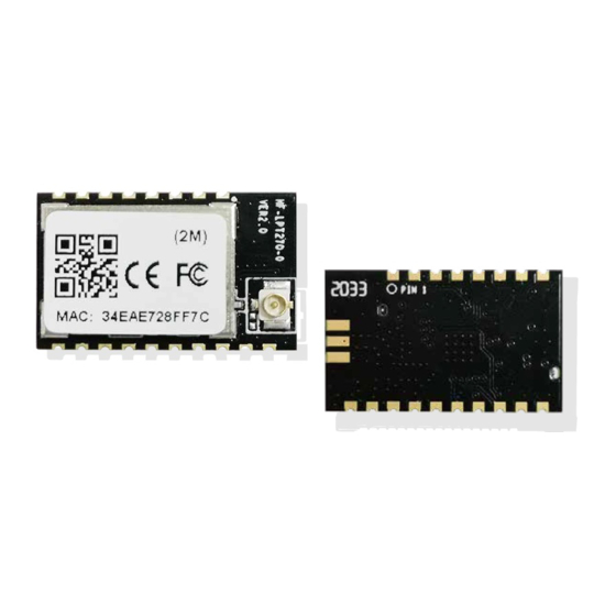
Page 7: Hardware Introduction
Support SDK for application develop Parameters Network Protocol IPv4, TCP/UDP/HTTP/TLS(SDK) AT+instruction set. SmartBLELink BLE Config User Configuration SmartAPLinkAPConfig SmartLink Config 1.2. Hardware Introduction HF-LPT270 Wi-Fi module appearance is as following. Figure 2. HF-LPT270-1Appearance - 7 - Shanghai High-Flying Electronics Technology Co., Ltd(www.hi-flying.com) -
Page 8: Hf-Lpt270 Pins Definition
Noneedof external RC reset circuit. Module Boot nReady “0” – Boot-up OK; Up Indicator “1” – Boot-up Fail; GPIO4, PWM2 12 Multi-Function nReload I,PU Detailed functions see <Notes> GPIO3, PWM3 - 8 - Shanghai High-Flying Electronics Technology Co., Ltd(www.hi-flying.com) - Page 9 After module is powered up, long press this button ( “Low” >4s ) and loose to make the module recover to factory setting. High-Flying strongly suggest customer fan out this pin to connector or button for “Manufacture” upgrade or “SmartLink” application.
-
Page 10: Electrical Characteristics
At normal mode, it’s Wi-Fi link status indicator.Output Low when STA mode connect to router AP or other STA connect to it when in AP mode. High-Flying strongly suggest customer fan out this pin to LED. UART1 Debug : Is used for debug log or firmware program, baud rate 921600. -
Page 11: Hf-Lpt270Mechanical Size
HF-LPX70 SeriesWi-Fi&BLE User Manual 1.2.3. HF-LPT270Mechanical Size HF-LPT270 modules physical size (Unit: mm) as follows: Figure 5. HF-LPT270 Mechanical Dimension - 11 - Shanghai High-Flying Electronics Technology Co., Ltd(www.hi-flying.com) -
Page 12: On-Board Chip Antenna
Antenna can’t be shieldedby any meal enclosure; All cover, include plastic, shall away from antenna at least 10mm; High-Flying suggest module better locate in following region at customer board, which to reduce the effect to antenna and wireless signal, and better consult High-Flying technical people when you structure your module placement and PCB layout. -
Page 13: Evaluation Kit
IPEX or populate directly 1.2.6. Evaluation Kit High-Flying provides the EVK to promote user to familiar the product and develop the detailed application. The evaluation kit shown as below, user can connect to module with the RS-232 UART, USB (Internal USB to UARTconvetor) or Wireless interface to configure the parameters, manage the module or do the some functional tests. - Page 14 HF-LPX70 SeriesWi-Fi&BLE User Manual Figure 8. HF-LPX70 EVKTypeOne Figure 9. HF-LPX70 EVKTypeTwo Notes: User need download USB to UART port driver from High-Flying web or contact with technical support people for more detail. The external interface description for evaluation kit as follows: Table5.
-
Page 15: Order Information
Button nRelo Smartlinkand Restore factory default configuration. SeemoreforPINDefinition 1.2.7. Order Information Base on customer detailed requirement, HF-LPT270 modules provide different variants and physical type for detailed application. Figure 10. HF-LPT270 Order Information - 15- Shanghai High-Flying Electronics Technology Co., Ltd(www.hi-flying.com) -
Page 16: Hardware Typical Application
HF-LPX70 SeriesWi-Fi&BLE User Manual 1.2.8. Hardware Typical Application Figure 11. HF-LPT270 Hardware Typical Application Notes: nReset- Module hardware reset signal. Input. Logics “0” effective. There is pull-up resister internal and no external pull-up required. When module power up or some issue happened, MCU need assert nRST signal “0”... -
Page 17: Appendix D:contact Information
© Copyright High-Flying, May, 2011 The information disclosed herein is proprietary to High-Flying and is not to be used by or disclosed to unauthorized persons without the written consent of High-Flying. The recipient of this document shall respect the security status of the information. -
Page 18: Oem/Integrators Installation Manual
This module can be used in IoT devices. The input voltage to the module should be nominally 3.3VDC and the ambient temperature of the module should not exceed 85℃. HF-LPT270 has one PCB antenna with max antenna gain 2.0dBi. If the antenna needs to be changed, the certification should be re-applied. - Page 19 9. Additional testing, Part 15 Subpart B disclaimer The final host / module combination need to be evaluated against the FCC Part 15B criteria for unintentional radiators in order to be properly authorized for operation as a Part 15 digital device. The host integrator installing this module into their product must ensure that the final composite product complies with the FCC requirements by a technical assessment or evaluation to the FCC rules, including the transmitter operation and should refer to guidance in KDB 996369.
Need help?
Do you have a question about the HF-LPT270 and is the answer not in the manual?
Questions and answers