Table of Contents
Advertisement
Quick Links
HF-LPT270 Series Wi-Fi&BLE User Manual
Low Power Wi-Fi + BLE Module
Overview of Characteristic
Support Wi-Fi IEEE802.11b/g/n and BLE5.0 Wireless Standards
Based on RISC SOC, 160MHz CPU, 276KB RAM, 2MB Flash
Support UART Data Communication with Wi-Fi or BLE
Support Wi-Fi STA/AP Mode
Support BLE SmartBLELink Config
Support Wi-Fi AP SmartAPLink and Sniffer SmartLink V8 Config
Support Wireless and Remote Firmware Upgrade Function
Support Software SDK for Develop
Support Different Antenna Option
HF-LPT270-0(F): External 1
Single +3.3V Power Supply for HF-LPT270-0(F)
Size:
HF-LPT270-0(F):22.5mm x 13.5mm x 3mm, SMT18 package
Shanghai High-Flying Electronics Technology Co., Ltd(www.hi-flying.com)
HF-LPT270
User Manual
V 1.0
st
IPEX or Antenna Pad Out
- 1 -
Advertisement
Table of Contents

Related Manuals for High-Flying HF-LPT270


Summary of Contents for High-Flying HF-LPT270
- Page 1 Support Different Antenna Option HF-LPT270-0(F): External 1 IPEX or Antenna Pad Out Single +3.3V Power Supply for HF-LPT270-0(F) Size: HF-LPT270-0(F):22.5mm x 13.5mm x 3mm, SMT18 package - 1 - Shanghai High-Flying Electronics Technology Co., Ltd(www.hi-flying.com)
-
Page 2: Table Of Contents
HF-LPT270 Series Wi-Fi&BLE User Manual TABLE OF CONTENTS LIST OF FIGURES ........................... 3 LIST OF TABLES ............................ 4 HISTORY ..............................5 PRODUCT OVERVIEW ........................ 6 1.1. General Description ......................... 6 1.1.1 Key Application ........................6 1.1.2 Device Paremeters ......................6 1.2. -
Page 3: List Of Figures
LIST OF FIGURES Figure1 HF-LPT270-0(F) Appearance ..................... 7 Figure 1. HF-LPT270-0(F) Pins Map ..................... 8 Figure 2. HF-LPT270-0(F)-2 Antenna PAD Out ..................9 Figure 3. HF-LPT270-0(F) Mechanical Dimension ................11 Figure 4. Suggested Module Placement Region ................. 12 Figure 5. 1 IPEX Connector ....................... -
Page 4: List Of Tables
HF-LPT270 Series Wi-Fi&BLE User Manual LIST OF TABLES Table1. HF-LPT270-0(F) Module Technical Specifications ..............6 Table2. HF-LPT270-0(F) Pins Definition ..................... 8 Table3. Absolute Maximum Ratings: ....................10 Table4. External Antenna Parameters ....................13 Table5. Evaluation Kit Interface Description ..................14 - 4 - Shanghai High-Flying Electronics Technology Co., Ltd(www.hi-flying.com) -
Page 5: History
HF-LPT270 Series Wi-Fi&BLE User Manual HISTORY Ed. V1.0 06-09-2020 First Version. - 5 - Shanghai High-Flying Electronics Technology Co., Ltd(www.hi-flying.com) -
Page 6: Product Overview
1. PRODUCT OVERVIEW 1.1. General Description The HF-LPT270-0(F) module is a fully self-contained small form-factor, single stream, 802.11b/g/n Wi-Fi + BLE module, which provide a wireless interface to any equipment with a Serial interface for data transfer. This module integrate MAC, baseband processor, RF transceiver with power amplifier in hardware and all Wi-Fi protocol and configuration functionality and networking stack, in embedded firmware to make a fully self-contained 802.11b/g/n Wi-Fi and BLE solution for a variety... -
Page 7: Hardware Introduction
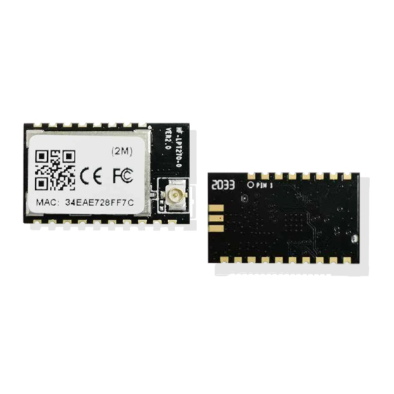
Support SDK for application develop Parameters Network Protocol IPv4, TCP/UDP/HTTP/TLS(SDK) AT+instruction set. SmartBLELink BLE Config User Configuration SmartAPLink AP Config SmartLink Config 1.2. Hardware Introduction HF-LPT270-0(F) Wi-Fi module appearance is as following. Figure1 HF-LPT270-0(F) Appearance - 7 - Shanghai High-Flying Electronics Technology Co., Ltd(www.hi-flying.com) -
Page 8: Hf-Lpt270-0(F) Pins Definition
HF-LPT270 Series Wi-Fi&BLE User Manual 1.2.1. HF-LPT270-0(F) Pins Definition Figure 1. HF-LPT270-0(F) Pins Map Table2. HF-LPT270-0(F) Pins Definition Describtion Net Name Signal Comments Type UART1_TX DEBUG_UART1_TX 3.3V TTL UART1 Debug Output GPIO17 UART1_RX DEBUG_UART1_RX 3.3V TTL UART1 Debug Input GPIO11... -
Page 9: Figure 2. Hf-Lpt270-0(F)-2 Antenna Pad Out
HF-LPT270 Series Wi-Fi&BLE User Manual Describtion Net Name Signal Comments Type GPIO4, PWM2 12 Multi-Function nReload I,PU Detailed functions see <Notes> GPIO3, PWM3 “0” – Wi-Fi connect to router Wi-Fi Status nLink “1” – Wi-Fi unconncted; Detailed functions see <Notes>... -
Page 10: Electrical Characteristics
HF-LPT270 Series Wi-Fi&BLE User Manual High-Flying strongly suggest customer fan out this pin to connector or button for “Manufacture” upgrade or “SmartLink” application. nReady Pin (LED) function(Low effective): OS initial finished indicator. Only after this pin output low, can the UART function be used. -
Page 11: Hf-Lpt270-0(F) Mechanical Size
HF-LPT270 Series Wi-Fi&BLE User Manual 1.2.3. HF-LPT270-0(F) Mechanical Size HF-LPT270-0(F) modules physical size (Unit: mm) as follows: Figure 3. HF-LPT270-0(F) Mechanical Dimension - 11 - Shanghai High-Flying Electronics Technology Co., Ltd(www.hi-flying.com) -
Page 12: On-Board Chip Antenna
Antenna can’t be shieldedby any meal enclosure; All cover, include plastic, shall away from antenna at least 10mm; High-Flying suggest module better locate in following region at customer board, which to reduce the effect to antenna and wireless signal, and better consult High-Flying technical people when you structure your module placement and PCB layout. -
Page 13: Evaluation Kit
I-PEX or populate directly 1.2.6. Evaluation Kit High-Flying provides the EVK to promote user to familiar the product and develop the detailed application. The evaluation kit shown as below, user can connect to module with the RS-232 UART, USB (Internal USB to UART convetor) or Wireless interface to configure the parameters, manage the module or do the some functional tests. -
Page 14: Order Information
HF-LPT270 Series Wi-Fi&BLE User Manual Figure 6. HF-LPX70 EVK Type Two Notes: User need download USB to UART port driver from High-Flying web or contact with technical support people for more detail. The external interface description for evaluation kit as follows: Table5. -
Page 15: Hardware Typical Application
HF-LPT270 Series Wi-Fi&BLE User Manual Figure 7. HF-LPT270 Order Information 1.2.8. Hardware Typical Application Notes: nReset- Module hardware reset signal. Input. Logics “0” effective. There is pull-up resister internal and no external pull-up required. When module power up or some issue happened, MCU need assert nRST signal “0”... - Page 16 HF-LPT270 Series Wi-Fi&BLE User Manual Warning 1.2.9 This equipment has been tested and found to comply with the limits for a Class B digital device, pursuant to Part 15 of the FCC Rules. These limits are designed to provide reasonable protection against harmful interference in a residential installation.
- Page 17 HF-LPT270 Series Wi-Fi&BLE User Manual Please notice that if the FCC identification number is not visible when the module is installed inside another device, then the outside of the device into which the module is installed must also display a label referring to the enclosed module.
-
Page 18: Appendix D: Contact Information
<END OF DOCUMENT> © Copyright High-Flying, May, 2011 The information disclosed herein is proprietary to High-Flying and is not to be used by or disclosed to unauthorized persons without the written consent of High-Flying. The recipient of this document shall respect the security status of the information.
Need help?
Do you have a question about the HF-LPT270 and is the answer not in the manual?
Questions and answers