Sign In
Upload
Manuals
Brands
High-Flying Manuals
Wireless Router
HF-LPB170
High-Flying HF-LPB170 Manuals
Manuals and User Guides for High-Flying HF-LPB170. We have
1
High-Flying HF-LPB170 manual available for free PDF download: User Manual
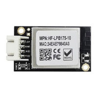
High-Flying HF-LPB170 User Manual (112 pages)
Low Power Wi-Fi + BLE Module
Brand:
High-Flying
| Category:
Wireless Router
| Size: 8 MB
Table of Contents
Table of Contents
3
List of Figures
9
List of Tables
11
History
12
1 Product Overview
13
General Description
13
Figure 1. Block Diagram
13
Device Paremeters
14
Key Application
14
Hardware Introduction
15
Figure 2. HF-LPT270-1 Appearance
16
Figure 3. HF-LPT270-0 Appearance
16
Figure 4. HF-LPT270-2 Appearance
16
Figure 5. HF-LPT170-10 Appearance
16
Figure 6. HF-LPT170-00 Appearance
17
Figure 7. HF-LPT271 V3 Appearance
17
Figure 8. HF-LPT271 V2 Appearance
17
Figure 10. HF-LPT272 Appearance
18
Figure 11. HF-LPB170 Appearance
18
Figure 12. HF-LPB175 Appearance
18
Figure 9. HF-LPT271-0 Appearance
18
Figure 13. HF-LPT570 Appearance
19
Figure 14. HF-LPT270 Pins Map
19
HF-LPT270 Pins Definition
19
Figure 15. HF-LPT270-PAD Antenna out
20
Figure 16. HF-LPT270-X-B/BR Pin Defination
21
Figure 17. HF-LPT170 Pins Map
21
HF-LPT170 Pins Definition
21
Figure 18. HF-LPT271 V3 Pins Map
22
HF-LPT271 Pins Definition
22
Figure 19. HF-LPT272 Pins Map
24
HF-LPT272 Pins Definition
24
Figure 20. HF-LPB170 Pins Map
25
HF-LPB170 Pins Definition
25
Figure 21. HF-LPB175 Pins Map
27
HF-LPB175 Pins Definition
27
Figure 22. HF-LPT570 Pins Map
28
HF-LPT570 Pins Definition
28
Figure 23. HF-LPT570 GPIO8 PIN
29
Electrical Characteristics
30
Figure 24. Power-On Sequence
30
Figure 25. Power-On Sequence Parameters
30
Power-On Sequence
30
Figure 26. HF-LPT270 Mechanical Dimension
32
HF-LPT270 Mechanical Size
32
Figure 27. HF-LPT170 Mechanical Dimension
33
HF-LPT170 Mechanical Size
33
Figure 28. HF-LPT271 Mechanical Dimension
34
HF-LPT271 Mechanical Size
34
Figure 29. HF-LPT272 Mechanical Dimension
35
HF-LPT272 Mechanical Size
35
Figure 30. HF-LPB170 Mechanical Dimension
36
HF-LPB170 Mechanical Size
36
Figure 31. HF-LPB175 Mechanical Dimension
37
HF-LPB175 Mechanical Size
37
Figure 32. HF-LPT570 Mechanical Dimension
38
Figure 33. Suggested Module Placement Region
38
HF-LPT570 Mechanical Size
38
On-Board Chip Antenna
38
Evaluation Kit
39
External Antenna
39
Figure 34. 1 St IPEX Connector
39
Figure 35. HF-LPX70 EVK
40
Order Information
40
Figure 36. HF-LPX70 Order Information
41
Figure 37. HF-LPT270 Hardware Typical Application
41
Hardware Typical Application
41
2 Functional Description
43
Wi-Fi Wireless Networking
43
Basic Wireless Network Based on AP
43
Wireless Network Based on STA
43
Figure 38. AP Wireless Network Structure
43
Wireless Network Based on AP+STA
44
BLE Connection
44
Figure 39. STA Network Structure
44
Figure 40. AP+STA Network Structure
44
Work Mode : Transparent Transmission Mode
45
Figure 41. BLE Connection
45
Registration Package Function
46
Heartbeat Package Function
46
Figure 42. Transparent Transmission Mode Registration Packet Function Transmission
46
Figure 43. Transparent Transmission Mode Registration Package Function Example
46
SOCKA HTTP Mode
47
Figure 44. Transparent Transmission Mode Heartbeat Packet Function Transmission
47
Figure 45. HTTP Mode Transmission
48
Figure 46. HTTP GET Request Example
49
SOCKA MQTT Mode
50
Figure 47. HTTP POST Request Example
50
UART Frame Scheme
51
Encryption
51
Figure 48. MQTT Concept
51
Parameters Configuration
52
Firmware Update
52
SOCKB Function
52
Figure 49. SOCKB Function Demo
52
Figure 50. Two Socket Data Separation
52
Multi-TCP Link Connection
53
Event Notification Function
53
MCU Firmware Upgrade
53
Figure 51. Multi-TCP Link Data Transmition Structure
53
A0: Set Firmware Download Http or Https URL
54
Firmare Upgrade Protocol
54
A1: Download Firmware into Module Flash
55
A2: Query Firmware MD5 in Flash
55
A4: Get Firmware from Module
55
3 Ble Communication
57
Service Uuid:0Xfee7
57
Module->APP, UART Notification Uuid:0Xfec8
57
APP->Module, UART Notification Uuid:0Xfec7
57
Module->APP, UART Indication Uuid:0Xfed6
57
APP->Module, UART Indication Uuid:0Xfed5
58
APP->Module, APP at Command Uuid:0Xfed4
58
4 Operation Guideline
59
Configuration
59
Open Web Management Interface
59
Figure 52. Open Web Management Page
59
System Page
60
Work Mode Page
60
Figure 53. System Web Page
60
Figure 54. Work Mode Page
60
STA Setting Page
61
Figure 55. STA Setting Page
61
Figure 56. STA Scan Page
61
AP Setting Page
62
Other Setting Page
62
Figure 57. AP Setting Page
62
Figure 58. Other Setting Page
62
Account Management Page
63
Upgrade Software Page
63
Restart Page
63
Figure 59. Account Page
63
Figure 60. Upgrade SW Page
63
Restore Page
64
Internal Webpage
64
Figure 61. Restart Page
64
Figure 62. Restore Page
64
Usage Introduction
65
Software Debug Tools
65
Network Connection
65
Default Parameter Setting
65
Figure 63. Internal Webpage
65
Figure 64. STA Interface Debug Connection
65
Figure 65. AP Interface Debug Connection
65
Module Debug
66
Figure 66. "Commtools" Serial Debug Tools
66
Figure 67. "Tcpudpdbg" Tools Create Connection
66
Typical Application Examples
67
Wireless Control Application
67
Figure 68. "Tcpudpdbg" Tools Setting
67
Figure 69. "Tcpudpdbg" Tools Connection
67
Figure 70. Wireless Control Application
67
Remote Management Application
68
Transparent Serial Port Application
68
Figure 71. Remote Management Application
68
Figure 72. Transparent Serial Port Application
68
5 At+Instruction Introduction
69
Configuration Mode
69
Switch to Configuration Mode
69
Figure 73. HF-LPT270 Default UART Port Parameters
69
Figure 74. Switch to Configuration Mode
69
Send at Command in Transparent Transmission Mode
70
At+Instruction Set Overview
70
Instruction Syntax Format
71
Figure 75. "AT+H" Instruction for Help
71
At+Instruction Special Character
72
Management Command
72
AT+: Null Command, Used for if Module in at Command Mode
72
AT+E: Open/Close Show Back Function
72
AT+CMDPW: Set/Query at Command Prefix Character for Sending at Command in Throughput Mode. Setting Is Valid after Reset
73
AT+WEL: Set/Query Boot Welcome Message
73
AT+EVENT: Set/Query Event Notification Function. Setting Is Valid after Reset
73
AT+ENTM: Set Module into Transparent Transmition Mode
74
AT+TMODE: Set/Query Module Data Transfer Mode. Setting Is Valid after Reset
74
AT+MID: Query Module ID Information
74
AT+WRMID: Set Module ID
74
AT+BTWAIT: Enable/Disable UART Booloader Function
75
AT+NDBGL: Enable/Disable UART Debug Information
75
AT+SMEM: Query the RAM Malloc Status
75
AT+FLASH: Set/Query Flash Content
76
AT+VER: Query Module Software Version Information
77
AT+WEBVER: Query Module Webpage Software Version Information
77
AT+Z: Restart Module
77
AT+H: Help
77
Factory Parameter Command
77
AT+RELD: Module Restore to Factory Default Setting
77
AT+FCLR: Erase Factory Setting
78
AT+CFGTF: Copy User Parameters to Factory Default Parameters
78
UART Parameter Command
78
AT+UART: Set/Query Serial Port Parameters. Setting Is Valid after Reset
78
AT+UARTTM: Set/Query the Two-Frame Time Interval When the Serial Port Receives Data
79
AT+UARTBUF: Set/Query the Maximum Serial Port Frame Size
79
Network Protocol Command
79
AT+PING: Network "PING" Instruction
79
AT+NETP: Set/Query SOCKA Network Protocol Parameters. Setting Is Valid Immediately
79
AT+NETPIDEN: Set/Query Whether Display from Which Communication Channel the Data Comes From, and the Setting will Take Effect after Reset
80
AT+NETPID: Set/Query the Communication Channel Number Tag Value
81
AT+MAXSK: Set/ Query SOCKA TCP Client Connection Number
81
AT+TCPLK: Query if SOCKA TCP Link Already Build-Up
82
AT+TCPTO: Set/Query SOCKA TCP Timeout; Setting Is Valid after Reset
82
AT+TCPDIS: Open/Close SOCKA TCP Client Link
82
AT+SEND: Send Data to SOCKA at Command Mode
83
AT+RECV: Receive Data from SOCKA at Command Mode
83
AT+SOCKB: Set/Query SOCKB Parameters. Setting Is Valid Immediately
83
AT+TCPDISB: Open/Close SOCKB TCP Client Link
84
AT+TCPTOB: Set/Query Operation SOCKB TCP Timeout. Setting Is Valid after Reset
84
AT+TCPLKB: Query SOCKB Connection Status
85
AT+SNDB: Send Datas to SOCKB at Command Mode
85
AT+RCVB: Receive Datas from SOCKB at Command Mode
85
AT+UDPLCPT: Set/Query UDP Local Port of SOCKA and SOCKB
85
AT+NREGEN: Set/Query Communication Channel Number Registration Package Function
86
AT+NREGDT: Set/Query Communication Channel Number Registration Package Function
86
AT+NREGSND: Set/Query the Transmission Method of the Communication Channel Number
86
Registration Package
86
AT+HEART: Set/Query Communication Channel Number Heartbeat Packet Data
87
SOCKA Channel HTTP Command (Need Set to HTTP Mode)
87
AT+HTPTP: Set/Query HTTP Request Type. Setting will Take Effect after Reset
87
AT+HTPURL: Set/Query HTTP Url Resources and Version. Setting will Take Effect after Reset
87
AT+HTPHEAD: Set/Query HTTP Header. Setting will Take Effect after Reset
88
AT+HTPPARA: Set/Query HTTP Parameters. Setting will Take Effect after Reset
88
SOCKA Channel MQTT Command (Need Set to MQTT Mode)
88
AT+MQTOPIC: Set/Query MQTT Topic Content. Setting will Take Effect after Reset
88
AT+MQLOGIN: Set/Query MQTT Login Content. Setting will Take Effect after Reset
89
AT+MQID: Set/Query MQTT Login Content. Setting will Take Effect after Reset
89
AT+MQPARA: Set/Query MQTT Parameters. Setting will Take Effect after Reset
89
Wi-Fi STA Command
89
AT+WSSSID: Set/Query Wi-Fi Associated AP SSID Parameters. Setting Is Valid after Reset
89
AT+WSKEY: Set/Query STA Security Parameters. Setting Is Valid after Reset
90
AT+WANN: Set/Query STA Network Setting. Setting Is Valid after Reset
90
AT+WSMAC: Set/Query Module STA MAC Address Parameters. Setting Is Valid after Reset
91
AT+WSLK: Query STA Wifi Link Status
91
AT+WSLKO: Query/Set STA Wifi Connection Order Function
91
AT+WSLQ: Query STA Wifi Signal Strength
91
AT+WSCAN: Scan AP, Max Show 50 Item
92
AT+WSCANS: Simplified Scan AP , Max Show 50 Item
93
AT+WSDNS: Set/Query STA Static DNS Server Address
93
Wi-Fi AP Command
94
AT+LANN: Set/Query Ap's Network Parameters. Setting Is Valid after Reset
94
AT+WAMAC: Set/Query Module AP and BLE MAC Address Parameters
94
AT+WAP: Set/Query AP Wi-Fi Parameters. Setting Is Valid after Reset
94
AT+WAKEY: Set/Query AP Wi-Fi Secruity Parameters. Setting Is Valid after Reset
95
AT+WADHCP: Set/Query AP DHCP Server Status; Setting Is Valid after Reset
95
AT+WALK: Query MAC Address of STA Device Connecting to Module AP
95
AT+WALKIND: Enable/Disable Indication of Module AP Connection Status
96
AT+WAPMXSTA: Set/Query Max STA Number Supported for AP
96
Other Wi-Fi Command
96
AT+WMODE: Set/Query Wi-Fi Work Mode. Setting Is Valid after Reset
96
AT+MDCH: Set Wi-Fi Auto Switch Function. Setting Is Valid after Reset
97
AT+ASWD: Set/Query Wifi Configuration Password
97
AT+DISPS: Set/Query Power Save Parameters
97
AT+WIFI: Enable/Disable Wi-Fi Command
97
AT+SMARTCONFIG: Config/Query Smart Config Method
98
AT+SMARTBTSTART: Start Smartblelink Function
98
AT+SMARTAPSTART: Start Smartaplink Function, Only Valid if Smartaplink Is Enabled
99
AT+SMTLK: Start Smartlink Function
99
AT+FIND: Config/Query Smartblelink Device Find Scheme
99
AT+WPS: Start WPS Function
99
AT+DTIM: Set/Query Wi-Fi DTIM
99
Upgrade Command
100
AT+OTA: Do Local OTA Upgrade
100
AT+UPURL: Set/ Query Remote Upgrade URL Address
100
Webpage Command
101
AT+PLANG: Set/Query Webpage Language Option
101
AT+WEBU: Set/ Query Webpage User Name and Password; Setting Is Valid after Reset
101
Network Time Protocol Command
101
AT+NTPRF: Set /Query Time Calibration Interval
101
AT+NTPEN: Enable/Disable Network Time Function. Setting Is Valid after Reset
101
AT+NTPTM: Query Network Time
102
AT+NTPSER: Set/Query NTP Server IP Address
102
BLE Command
102
AT+BLE: Config/Query BLE UART Throughput Function
102
AT+BLENAME: Config/Query BLE Broadcast Name, Valid Afterreboot
103
AT+BLENTFUUIDS: Config/Query BLE Notification UUID
103
AT+BLENTFUUIDR: Config/Query BLE Notification Receive UUID
103
AT+BLENTFUUIDW: Config/Query BLE Notification Write UUID
104
AT+BLEINDUUIDR: Config/Query BLE Indication Receive UUID
104
AT+BLEINDUUIDW: Config/Query BLE Indication Write UUID
104
AT+BLECON: Config/Query BLE Connection Parameters
105
AT+BLEADP: Config/Query BLE Advertising Parameters
105
AT+BLEADV: Config/Query BLE Advertising Content
105
6 Smt Information
107
Recommended Reflow Profile
107
Device Handling Instruction (Module IC SMT Preparation)
107
Figure 76. Reflow Soldering Profile
107
Appendix A: Hw Reference Design
108
Appendix B: Tcp Raw Http Packet Transfer
109
Sending HTTP Raw Data in Throughput Mode
109
Appendix C:references
111
C.1.High-Flying Mass Production Tool
111
C.2.Smartblelink
111
Advertisement
Advertisement
Related Products
High-Flying HF-LPB100
High-Flying HF-LPB120
High-Flying HF-LPD100
High-Flying HF-LPT271
High-Flying HF-LPX70 Series
High-Flying HF-LPT170
High-Flying HF-LPT272
High-Flying HF-LPB175
High-Flying HF-LPT570
High-Flying HF-LPB125
High-Flying Categories
Wireless Router
Control Unit
Wireless modules
Network Card
Solar panel
More High-Flying Manuals
Login
Sign In
OR
Sign in with Facebook
Sign in with Google
Upload manual
Upload from disk
Upload from URL