Advertisement
Quick Links
HF-LPD100 Low Power WiFi Module User Manual
802.11a/b/g/n WiFi Module User Manual
Overview of Characteristic
Support IEEE802.11 a/b/g/n Wireless Standards, work in 2.4GHz and 5GHz dual band
Based on Andes Core, 160MHz CPU, 192KB RAM, 2MB or 8MB Flash
Support UART Data Communication Interface
Support Work As STA/AP/AP+STA Mode
Support Sniffer Method SmartLink V8 Config
Support SoftAP Method SmartAPLink Config
Support WeChat Airkiss 2.0
Support Wireless and Remote Firmware Upgrade Function
Support Software SDK for Develop
Support Different Antenna Option
HF-LPD100:Internal PCB
High-Flying Electronics Technology Co., Ltd.(www.hi-flying.com)
HF-LPD100
V 1.3
HF-LPD100
Advertisement

Related Manuals for High-Flying HF-LPD100


Summary of Contents for High-Flying HF-LPD100
- Page 1 HF-LPD100 Low Power WiFi Module User Manual HF-LPD100 802.11a/b/g/n WiFi Module User Manual V 1.3 HF-LPD100 Overview of Characteristic Support IEEE802.11 a/b/g/n Wireless Standards, work in 2.4GHz and 5GHz dual band Based on Andes Core, 160MHz CPU, 192KB RAM, 2MB or 8MB Flash ...
- Page 2 HF-LPD100 Low Power WiFi Module User Manual Single +3.3V Power Supply Size: HF-LPD100: 23.1mm x 32.8mm x 3.5mm, SMT48 package FCC/CE/SRRC/RoHS Certificated (TBD) High-Flying Electronics Technology Co., Ltd.(www.hi-flying.com)
- Page 3 HF-LPD100 Low Power WiFi Module User Manual HISTORY Ed. V0.1 08-24-2017 Internal Version. Ed. V1.0 10-26-2018 Released Version Ed. V1.1 06-04-2019 Add HF-LPD130 Version Ed. V1.2 09-29-2019 Add HF-LPD100 external pin antenna Ed. V1.3 11-13-2019 Update PIN definition. High-Flying Electronics Technology Co., Ltd.(www.hi-flying.com)
-
Page 4: Product Overview
1. PRODUCT OVERVIEW 1.1. General Description The HF-LPD100 support 2.4GHz and 5GHz dual band. It is a fully self-contained small form-factor, single stream, 802.11a/b/g/n Wi-Fi module, which provide a wireless interface to any equipment with a Serial interface for data transfer.HF-LPD100 integrate MAC, baseband processor, RF transceiver with power amplifier in hardware and all Wi-Fi protocol and configuration functionality and networking stack, in embedded firmware to make a fully self-contained 802.11b/g/n Wi-Fi solution for a variety of... - Page 5 HF-LPD100 Low Power WiFi Module User Manual 1.1.2 Device Paremeters Table1. HF-LPD100 Module Technical Specifications Class Item Parameters Certification 2.4GHz:802.11 b/g/n Wireless standard 5GHz:802.11 a /n 2.4G Wi-Fi:2412-2462 MHz Frequency range 5G Wi-Fi B1: 5180-5240MHz, B4: 5745-5825MHz 802.11b:20.76dBm ;802.11g:21.94dBm 802.11n20:20.62dBm;802.11n40:21.10dBm 2.4G Transmit Power...
-
Page 6: Hardware Introduction
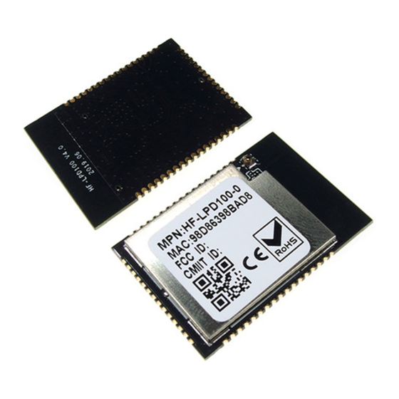
HF-LPD100 Low Power WiFi Module User Manual 1.2. Hardware Introduction HF-LPD100 series Wi-Fi module appearance is as following. Figure 1. HF-LPD100 Appearance 1.2.1. HF-LPD100 Pins Definition Figure 2. HF-LPD100 Pins Map Table2. HF-LPD100 Pins Definition Describtion Net Name Signal Comments Type High-Flying Electronics Technology Co., Ltd.(www.hi-flying.com) - Page 7 HF-LPD100 Low Power WiFi Module User Manual Describtion Net Name Signal Comments Type 1,17,18 Ground Power 34,35,37 GPIO00 GPIO00 PWM0 GPIO01 GPIO01 PWM1 USB+ HSDP USB 2.0 USB- HSDN USB 2.0 TEST Test only. Leave it unconnected. TEST Test only. Leave it unconnected.
- Page 8 After module is powered up, long press this button ( “Low” > 4s ) and loose to make the module recover to factory setting. High-Flying strongly suggest customer fan out this pin to connector or button for “Manufacture” upgrade or “ SmartLink” application.
- Page 9 HF-LPD100 Low Power WiFi Module User Manual 1.2.2. Electrical Characteristics Table3. Absolute Maximum Ratings: Parameter Condition Min. Typ. Max. Unit Work temperature range °C Maximum soldering temperature IPC/JEDEC J-STD-020 °C ESD (Human Body Model HBM) TAMB=25°C ESD (MM) TAMB=25°C 0.25 Table4.
- Page 10 Figure 3. HF-LPD100-1 and -0 Mechanical Dimension 1.2.4. HF-LPD100 On-board PCB Antenna HF-LPD100 module support internal on-board PCB antenna option. When customer select internal antenna, you shall comply with following antenna design rules and module location suggestions: For customer PCB, RED color region (8.3x18.4mm) can’t put componet or paste GND net;...
- Page 11 PCB layout. 1.2.5. Evaluation Kit High-Flying provides the evaluation kit to promote user to familiar the product and develop the detailed application. The evaluation kit shown as below, user can connect to HF-LPD100 series module with the RS-232 UART, USB (Internal USB to UART convetor) or Wireless interface to configure the parameters, manage the module or do the some functional tests.
- Page 12 HF-LPD100 Low Power WiFi Module User Manual The external interface description for evaluation kit as follows: Table6. HF-LPD100 Evaluation Kit Interface Description Function Name Description External RS232 Main data/command RS-232 interface Interface USB to UART interface, can be used for debug UART log DC jack for power in, 5~9V input.
-
Page 13: Package Information
HF-LPD100 Low Power WiFi Module User Manual 2. PACKAGE INFORMATION 2.1. Recommended Reflow Profile Figure 7. Reflow Soldering Profile Table7. Reflow Soldering Parameter Item Temperature (Degree) Time(Sec) Reflow Time Time of above 220 35~55 sec Peak-Temp 260 max Note: 1. Recommend to supply N2 for reflow oven. - Page 14 HF-LPD100 Low Power WiFi Module User Manual 2.3. HF-LPD100 Shipping Information TAPE Size: 340*340*50 mm Size: 370*370*370 mm Figure 8. HF-LPD100 Shipping Information Note: 1 tape = 900pcs 1 box = 5 tapes = 5 * 900 pcs = 4500pcs...
- Page 15 OEM Guidance Applicable FCC rules This module is granted by Single Modular Approval. It complies to the requirements of FCC part 15.247 and 15.407 2. The specific operational use conditions This module can be used in IoT devices. The input voltage to the module is nominally 2.1~3.46V DC.
- Page 16 8. Information on test modes and additional testing requirements a)The modular transmitter has been fully tested by the module grantee on the required number of channels,modulation types, and modes, it should not be necessary for the host installer to re-test all the available transmitter modes or settings. It is recommended that the host product manufacturer, installing the modular transmitter,perform some investigative measurements to confirm that the resulting composite system does not exceed the spurious emissions limits or band edge limits (e.g., where a different antenna may be causing...
Need help?
Do you have a question about the HF-LPD100 and is the answer not in the manual?
Questions and answers