Advertisement
www.ti.com
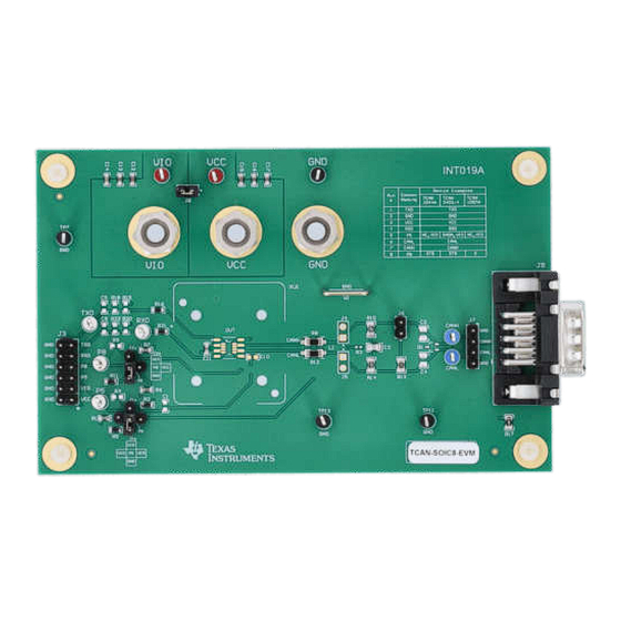
EVM User's Guide: TCAN-SOIC8-EVM
Universal 8-pin CAN Evaluation Module
Description
The universal 8-pin CAN EVM provides users with the
ability to evaluate all of TI's 8-pin CAN transceiver
families. The universal 8-pin CAN EVM is configurable
for use with all TI 8-pin CAN transceiver families by
populating the transceiver and setting jumpers on the
EVM.
This EVM also has the footprints for a SIC network,
to the CAN bus lines via user-installed J4 and J5.
Connecting the SIC network to CANH and CANL
simulates a noisy CAN bus by adding more reflections
and ringing to the signals. This can be used to
test the reliability of the transceiver in a very noisy
environment.
SLLU385 – JULY 2024
Submit Document Feedback
Features
•
Standard and split termination on the CAN bus
•
Footprints for filter capacitors, common-mode
choke, and TVS diode for CAN bus protection from
RF noise and transient pulses
•
Footprints for common 8-pin SOIC socket, and
CAN FD SIC loading
•
DSUB9 connector with the CAN bus signals
and GND for typical automotive cable harness
connections
•
All digital signals for configuration and control
brought out to a header for easy access
•
Multifunctional jumpers for different functional use
of generic pins
TCAN-SOIC8-EVM
Copyright © 2024 Texas Instruments Incorporated
Description
Universal 8-pin CAN Evaluation Module
1
Advertisement
Table of Contents

Subscribe to Our Youtube Channel
Related Manuals for Texas Instruments TCAN-SOIC8-EVM


Summary of Contents for Texas Instruments TCAN-SOIC8-EVM
- Page 1 • Multifunctional jumpers for different functional use test the reliability of the transceiver in a very noisy of generic pins environment. TCAN-SOIC8-EVM SLLU385 – JULY 2024 Universal 8-pin CAN Evaluation Module Submit Document Feedback Copyright © 2024 Texas Instruments Incorporated...
-
Page 2: Kit Contents
ESD protection, and capacitors for further EMC protection, or signal conditioning. A DSUB9 connector is included to allow the evaluation and use of the CAN bus in larger systems. Universal 8-pin CAN Evaluation Module SLLU385 – JULY 2024 Submit Document Feedback Copyright © 2024 Texas Instruments Incorporated... -
Page 3: Jumper Information
TXD, Device pin 1 test point Test point RXD, Device pin 4 test point TP7, GND test points TP8, TP11, TP12 test point TP10 test point SLLU385 – JULY 2024 Universal 8-pin CAN Evaluation Module Submit Document Feedback Copyright © 2024 Texas Instruments Incorporated... - Page 4 0Ω series resistor, R16. An optional pullup resistor to VIO can be installed on R15, an optional pulldown resistor to GND can be installed on R18, and an optional filtering capacitor can be installed on Universal 8-pin CAN Evaluation Module SLLU385 – JULY 2024 Submit Document Feedback Copyright © 2024 Texas Instruments Incorporated...
- Page 5 Open Drain Output (FAULT): If the device and application use pin 5 as an open drain output, then external pullup is required. Set J1 as either a pullup to V or V SLLU385 – JULY 2024 Universal 8-pin CAN Evaluation Module Submit Document Feedback Copyright © 2024 Texas Instruments Incorporated...
- Page 6 Bus filtering caps transient protection To add extra protection for system level transients and ESD protection, Transient and ESD protection D1 populated with ESD2CAN24-Q1 Universal 8-pin CAN Evaluation Module SLLU385 – JULY 2024 Submit Document Feedback Copyright © 2024 Texas Instruments Incorporated...
- Page 7 SW, R , S, Input R6/R7 (J2) R9/R11 (J2) installable for use with slope mode on devices with R pin. No Connect SLLU385 – JULY 2024 Universal 8-pin CAN Evaluation Module Submit Document Feedback Copyright © 2024 Texas Instruments Incorporated...
- Page 8 100nF 10uF 1µF 0.1uF D3082-05 100V 100V If P5 <-> VIO: Populate C10 (no socket) or C18 (socket) Figure 3-1. EVM Schematic Universal 8-pin CAN Evaluation Module SLLU385 – JULY 2024 Submit Document Feedback Copyright © 2024 Texas Instruments Incorporated...
-
Page 9: Pcb Layouts
Hardware Design Files 3.2 PCB Layouts Figure 3-2. EVM Layout (Top View) Figure 3-3. EVM Layout (Bottom View) SLLU385 – JULY 2024 Universal 8-pin CAN Evaluation Module Submit Document Feedback Copyright © 2024 Texas Instruments Incorporated... - Page 10 R1, R6, R7 4.7k CRCW06034K70JNEA Vishay-Dale 0603 R2, R5, R11, R16, RES, 0, 0%, 0.25 W, AEC-Q200 Grade 0, 0603 603 PMR03EZPJ000 Rohm Universal 8-pin CAN Evaluation Module SLLU385 – JULY 2024 Submit Document Feedback Copyright © 2024 Texas Instruments Incorporated...
- Page 11 Header, 100mil, 2x1, Gold, TH 2x1 Header TSW-102-07-G-S Samtec SMD, 4-Leads, Body 4.7 x 100uH Inductor, Ferrite, 100uH, 0.15A, 2 ohm, SMD ACT45B-101-2P-TL003 3.7mm SLLU385 – JULY 2024 Universal 8-pin CAN Evaluation Module Submit Document Feedback Copyright © 2024 Texas Instruments Incorporated...
- Page 12 U-SOT Automotive High Speed CAN Transceiver SOT23-8 TCAN1044DDFRQ1 Texas Instruments Socket, SOIC-8, 1.27mm Socket, SOIC-8, 1.27mm Pitch SK02-0008SOP-QS-01A RS Tech Incorporated Pitch Universal 8-pin CAN Evaluation Module SLLU385 – JULY 2024 Submit Document Feedback Copyright © 2024 Texas Instruments Incorporated...
-
Page 13: Additional Information
All TI's 8-pin CAN transceivers supported by this EVM are listed on ti.com: transceivers. 4.1 Trademarks All trademarks are the property of their respective owners. SLLU385 – JULY 2024 Universal 8-pin CAN Evaluation Module Submit Document Feedback Copyright © 2024 Texas Instruments Incorporated... - Page 14 STANDARD TERMS FOR EVALUATION MODULES Delivery: TI delivers TI evaluation boards, kits, or modules, including any accompanying demonstration software, components, and/or documentation which may be provided together or separately (collectively, an “EVM” or “EVMs”) to the User (“User”) in accordance with the terms set forth herein.
- Page 15 www.ti.com Regulatory Notices: 3.1 United States 3.1.1 Notice applicable to EVMs not FCC-Approved: FCC NOTICE: This kit is designed to allow product developers to evaluate electronic components, circuitry, or software associated with the kit to determine whether to incorporate such items in a finished product and software developers to write software applications for use with the end product.
- Page 16 www.ti.com Concernant les EVMs avec antennes détachables Conformément à la réglementation d'Industrie Canada, le présent émetteur radio peut fonctionner avec une antenne d'un type et d'un gain maximal (ou inférieur) approuvé pour l'émetteur par Industrie Canada. Dans le but de réduire les risques de brouillage radioélectrique à...
- Page 17 www.ti.com EVM Use Restrictions and Warnings: 4.1 EVMS ARE NOT FOR USE IN FUNCTIONAL SAFETY AND/OR SAFETY CRITICAL EVALUATIONS, INCLUDING BUT NOT LIMITED TO EVALUATIONS OF LIFE SUPPORT APPLICATIONS. 4.2 User must read and apply the user guide and other available documentation provided by TI regarding the EVM prior to handling or using the EVM, including without limitation any warning or restriction notices.
- Page 18 Notwithstanding the foregoing, any judgment may be enforced in any United States or foreign court, and TI may seek injunctive relief in any United States or foreign court. Mailing Address: Texas Instruments, Post Office Box 655303, Dallas, Texas 75265 Copyright © 2023, Texas Instruments Incorporated...
- Page 19 TI products. TI’s provision of these resources does not expand or otherwise alter TI’s applicable warranties or warranty disclaimers for TI products. TI objects to and rejects any additional or different terms you may have proposed. IMPORTANT NOTICE Mailing Address: Texas Instruments, Post Office Box 655303, Dallas, Texas 75265 Copyright © 2024, Texas Instruments Incorporated...
Need help?
Do you have a question about the TCAN-SOIC8-EVM and is the answer not in the manual?
Questions and answers