Advertisement
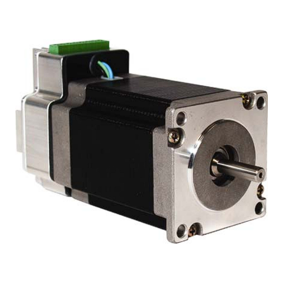
The AMCI Integrated Stepper Motor and Microstepping Drive Combination
represents the future of Stepper Motor Control applications.
Features
Optimized motor and drive combination
Industry standard Step/Direction control signals
More torque than competitive designs
Eliminates the need for a separate stepper drive
Wide range of operating voltages, 24-75Vdc
Speeds to 2000 RPM
Anti-resonance circuitry
Easy to use configuration software
Uses standard RS232 interface for programming
Programmable motor current
Programmable Idle Current Reduction
400, 1000, 2000, or 5000 selectable step resolution
AMCI quality and reliability
Single power supply
20 Gear Drive, Plymouth Industrial Park, Terryville, CT 06786
Tel: (860) 585-1254
Fax: (860) 584-1973
SMD Series
Integrated Stepper Driver and Motor
Revision 1.3
The SMD is a self-contained stepper motor and
driver package, capable of optimizing a wide
variety of industrial stepper motor control
applications. It is no longer necessary to run a
cable from the indexer to the driver and then a
cable from the driver to the motor. Now you
simply have to connect the step and direction
signals, along with supply voltage, directly to the
SMD and your installation is complete.
Web: www.amci.com
page: 1
Advertisement
Table of Contents

Related Manuals for AMCI SMD Series


Summary of Contents for AMCI SMD Series
- Page 1 SMD Series Integrated Stepper Driver and Motor Revision 1.3 The AMCI Integrated Stepper Motor and Microstepping Drive Combination represents the future of Stepper Motor Control applications. The SMD is a self-contained stepper motor and driver package, capable of optimizing a wide variety of industrial stepper motor control applications.
-
Page 2: Technical Specifications
Integrated Stepper Driver and Motor Revision 1.3 The SMD uses step and direction control signals generated from an external source. (i.e. AMCI’s 3202 or 3601 stepper control modules) It is powered by an external DC supply with an operating range of 24 to 75Vdc. There are additional control pins that can be used to disable the motor. -
Page 3: Electrical Specifications
Disable – Disables motion and disables current to motor Type of input – 5V TTL logic Input Current – 15mA max Input Connector – AMCI Part # MS-8P, provided (Phoenix part # MC 1.5/8-ST3.81) 8 screw terminal type – 16 AWG max. Programming Communications Interface –... - Page 4 SMD Series Integrated Stepper Driver and Motor Revision 1.3 SMD23 Torque Curves 20 Gear Drive, Plymouth Industrial Park, Terryville, CT 06786 page: 4 Tel: (860) 585-1254 Fax: (860) 584-1973 Web: www.amci.com...
- Page 5 SMD Series Integrated Stepper Driver and Motor Revision 1.3 SMD34 Torque Curves 20 Gear Drive, Plymouth Industrial Park, Terryville, CT 06786 page: 5 Tel: (860) 585-1254 Fax: (860) 584-1973 Web: www.amci.com...
- Page 6 SMD Series Integrated Stepper Driver and Motor Revision 1.3 NOTE: Current setting for each torque curve was measured at 3.4Arms. 20 Gear Drive, Plymouth Industrial Park, Terryville, CT 06786 page: 6 Tel: (860) 585-1254 Fax: (860) 584-1973 Web: www.amci.com...
-
Page 7: Installation
SMD Series Integrated Stepper Driver and Motor Revision 1.3 INSTALLATION The mounting flange functions as both a mounting mechanism and also a heatsink. Mount the SMD to a large as possible thermally conductive surface. Heat is conducted from the SMD to the mounting fixture resulting in motor/drive cooling. - Page 8 SMD Series Integrated Stepper Driver and Motor Revision 1.3 SMD34 Outline Drawing 20 Gear Drive, Plymouth Industrial Park, Terryville, CT 06786 page: 8 Tel: (860) 585-1254 Fax: (860) 584-1973 Web: www.amci.com...
- Page 9 Logic inputs are rated for 5Vdc max. Exceeding 5vdc will damage the unit unless the recommended limiting resistors are used. Control Signal Wiring Programmer Wiring – CSMD-5 cable SMD Connector – AMCI part # MS-8P Serial Port Connector – DB-9 To SMD To PC Serial Port 1.
- Page 10 SMD Series Integrated Stepper Driver and Motor Revision 1.3 Wiring the SMD Control Signals to a Single-Ended Input The SMD is built with differential inputs for optimal noise immunity. However many stepper control circuits use single-ended (sinking or sourcing) control signals. The following schematics show the correct wiring when using the SMD with single-ended control signals.
- Page 11 Power supply – 24 to 75VDC, 4Amps; • Programming cable - AMCI CSMD-5, 5 ft serial cable(optional). It connects the driver to a PC. The connections are described in the document. The driver circuit provides optical isolation from the PC;...
- Page 12 SMD Series Integrated Stepper Driver and Motor Revision 1.3 6. Select the Port menu and choose the COM port that the cable is connected to: 7. Turn on the power supply to the driver. 8. Press the Connect button. For a few seconds the TX and the RX lights can change their color to green to inform that the program is establishing the communication.
-
Page 13: Error Messages
SMD Series Integrated Stepper Driver and Motor Revision 1.3 The firmware version Status display 9. If a change to a setting is required, the new setting is selected from the appropriate field. By pressing the Defaults button, the default settings will appear: •... - Page 14 [18] months. Within this warranty period, AMCI shall, at its option, repair or replace, free of charge, any equipment covered by this warranty which is returned, shipping charges prepaid, within one year from date of invoice, and which upon examination proves to be defective in material or workmanship and not caused by accident, misuse, neglect, alteration, improper installation or improper testing.
Need help?
Do you have a question about the SMD Series and is the answer not in the manual?
Questions and answers