Table of Contents
Advertisement
Quick Links
Advertisement
Table of Contents

Related Manuals for AMCI SV160E2


Summary of Contents for AMCI SV160E2
- Page 1 ADVANCED MICRO CONTROLS INC. Manual #: 940-0S252 E2 Technology...
-
Page 2: General Information
[18] months. Within this warranty period, AMCI shall, at its option, repair or replace, free of charge, any equipment covered by this warranty which is returned, shipping charges prepaid, within eighteen months from date of invoice, and which upon examination proves to be defective in material or workmanship and not caused by accident, misuse, neglect, alteration, improper installation or improper testing. -
Page 3: Table Of Contents
Immediate Stops ....29 Basic Functionality ......18 Absolute Move ......30 Additional Functionality ....18 Controlled Stops ....30 Immediate Stops ....30 20 Gear Drive, Plymouth Ind. Park, Terryville, CT 06786 Tel: (860) 585-1254 Fax: (860) 584-1973 http://www.amci.com... - Page 4 Variable Definitions ...... 37 Reference: Command Mode Data Total Time Equations ....39 Format Reference: Homing an SV160E2 Command Bits Must Transition ....57 Definition of Home Position ....41 Data Format ..........57 Definition of Homing Speed ....41 Output Data Format ........
- Page 5 Install the EDS File ....... 98 Operating Temperature Guidelines ..79 Host System Configuration ...... 100 Mounting ..........79 Add the SV160E2 to Your Project ... 100 SV160E2 Outline Drawing .... 80 SV160E2 Properties Setup ....... 101 SV160E2 Mounting ....... 80 General Tab ........
- Page 6 Configure the SV160E2 ......116 Set the I/O Configuration ......117 Set the SV160E2 Device Name ....118 Verify and Download the New Configuration ......... 118 MRP Installations ........119 Configure the SV160E2 as an MRC ..119 ADVANCED MICRO CONTROLS INC.
-
Page 7: About This Manual
Applicable Units This manual applies to all of the units in the SV160E2 family. Each unit contains a two port Ethernet switch, which simplifies network wiring. When the EtherNet/IP protocol is used, the unit can act as a node in a Device Level Ring (DLR). -
Page 8: Manual Conventions
Manual Conventions Trademarks and Other Legal Stuff The AMCI logo is a trademark of Advanced Micro Controls Inc. “CIP” is a trademark of Open DeviceNet Vendor Association, Inc. “EtherNet/IP” is a trademark of ControlNet International, Ltd. under license by Open DeviceNet Vendor Association, Inc. “PROFINET” is a registered trademark of PROFIBUS & PROFI- NET International (PI). -
Page 9: Manual Layout
If you need to install and use an Integrated Servo Motor product from AMCI, then the rest of the man- ual is written for you. To simplify installation and configuration, the rest of the manual is broken down into references and tasks. - Page 10 SV160E2 User Manual BOUT THIS ANUAL Notes ADVANCED MICRO CONTROLS INC.
-
Page 11: Reference: Sv160E2 Specifications
E2 Product Family The SV160E2 is an addition to the family of E2 products from AMCI. E2 products incorporate E2 Technol- ogy, a common Ethernet network interface that allows them to operate over the EtherNet/IP, Modbus TCP, and PROFINET industrial networks. The E2 product family encompasses stepper and servo integrated motion control products, resolver based encoder products, and specialty I/O products for sensor interface and motion control. -
Page 12: Safe Torque Off Functionality
The MRP interface eliminates single point failures in PROFINET environments. An SV160E2 is powered by a nominal 48 to 80 Vdc power source, and can accept surge voltages of up to 100 Vdc without damage. The continuous motor torque is fully programmable from 0.1 Nm to 0.50 Nm with the Continuous Torque Limit parameter. -
Page 13: Specifications
16 AWG max. 0.197 inches Screw Terminals Cable AMCI Part # Length Ethernet CNER-5M 5 meter Digital I/O CNFL-5M 5 meter Power CNGL-5M 5 meter 20 Gear Drive, Plymouth Ind. Park, Terryville, CT 06786 Tel: (860) 585-1254 Fax: (860) 584-1973 http://www.amci.com... -
Page 14: Indexer Functionality
SV160E2 S SV160E2 User Manual PECIFICATIONS Indexer Functionality The table below lists the functionality offered by the indexer built into the AMCI SV160E2 units. Feature Description The SV160E2 units can be configured to communicate with EtherNet/IP, Multiple Network PROFINET, or Modbus TCP protocols. This allows easy setup and ... -
Page 15: Servo Control
The optimum PID values for the current loop are solely dependant on motor characteris- tics. These values are set at the factory during the final test of the SV160E2 and are stored in the device’s flash memory. In order to simplify programming, these current loop values are not available to the end user since they are optimized at the factory. -
Page 16: Absolute Encoder
The second is with a sensor mounted on the machine. When you define one of the inputs as the Home Input, you can issue commands to the SV160E2 that will cause the unit to seek this sensor. How the SV160E2 actu-... -
Page 17: Start Indexed Move Input
26, is used to decelerate the load. If a stall is not detected during the stop, the motor will return to the Profile Position value. If a stall is detected during the stop, the SV160E2 will disable the motor and issue a Position_Invalid fault. -
Page 18: Sto Option
This state cannot be overridden by software control. Inputs 3 and 4 are used as the redundant STO inputs. When an SV160E2 is ordered with the STO functional- ity, additional components are added to the PC board that directly connects these two inputs to the power stage of the motor. -
Page 19: Status Led's
PECIFICATIONS Status LED’s Each SV160E2 has three status LED’s. As shown in figure R1.4, these LED’s are located on the rear cover. Drive Status LED The Drive Status LED is a bi-color red/green LED. This LED shows the state of the unit as a whole. -
Page 20: Network Status (Ns) Led
Figure R1.6 shows the pinout of the Ethernet connectors when POWER: 48 to 80 Vdc viewed from the back of the SV160E2. Each Ethernet port on the SV160E2 is an “auto-sense” port that will automatically switch between 10baseT and 100baseT depending on the network equip- ment it is attached to. -
Page 21: Digital Inputs Connector
Figure R1.8 M12 Power Connector +DC Power and DC Common are used to power the SV160E2. The Ext. Brake Resistor pin is for an external braking resistor that is used to dissipate regeneration energy during deceleration. The Chassis GND pin should be used to ground the chassis of the motor if it is not grounded through its mounting. -
Page 22: Torque And Power Curves
The power supply should be sized base on the peak current that the motor can draw during a move. This value is programmable through the Peak Torque Limit and has a maximum value of 13.0 amps. The SV160E2 has a torque constant of 0.124 Nm/A. -
Page 23: Regeneration (Back Emf) Effects
An external braking resistor and control circuitry can be added to the system. The power switches in the SV160E2 units can conduct a maxi- mum of 10 amps, so the sum of the motor current and braking resistor circuit currents must be below this value. -
Page 24: Compatible Connectors And Cordsets
Many different connectors and cordsets are available on the market, all of which will work with the SV160E2 provided that the manufacturer follows the connector and Ethernet standards. AMCI has reviewed the following connectors and ethernet cordsets for compatibility with the SV160E2. -
Page 25: Definitions
To convert from steps/second to steps/second/millisecond, divide the value by 1000. This must be done when converting from a value used in the equations to a value programmed into an SV160E2. To convert from steps/second/millisecond to steps/second , multiply the value by 1000. This must be done when converting from the value programmed into an SV160E2 to the value used in the equations. -
Page 26: Home Position
In order to limit regenerative energy when decelerating a large inertial load, the SV160E2 allows you to pro- gram a deceleration rate for immediate stops. If left at its default value of zero, the SV160E2 stop all motion immediately. When programmed to a value between 1,500 and 15,999, the SV160E2 will decelerate at a rate of 1,500,000 to 15,999,000 steps/sec . -
Page 27: A Simple Move
Programmed Speed. Both the Acceleration Value and the Programmed Speed are programmed when the move command is sent to the SV160E2. 2) The motor continues to run at the Programmed Speed until it reaches the point where it must decelerate before reaching point B at zero speed. -
Page 28: Controlled And Immediate Stops
If a stall is not detected during the stop, the motor will return to the Profile Position value. If a stall is detected during the stop the SV160E2 will disable the motor and issue a Position_Invalid fault. See Stall Detection on page 16 for a description of the stall detection process. -
Page 29: Basic Move Types
When the command is accepted, the axis will immediately decelerate at the programmed rate and stop. When stopped successfully, the SV160E2 will set a In_Hold_State bit in the input data table. The Relative Move can be restarted with the Resume Move command from the host controller or the move can be aborted by starting another move. -
Page 30: Absolute Move
Absolute Move Absolute Moves move from the current Profile Posi- tion (A) to a given position (B). (The SV160E2 calcu- lates the direction and number of steps needed to move to the given position and moves that number of steps.) -
Page 31: Cw/Ccw Jog Move
Limit Switch. For example, it is possible to start a CW Jog Move while the CCW Limit Switch is active. 20 Gear Drive, Plymouth Ind. Park, Terryville, CT 06786 Tel: (860) 585-1254 Fax: (860) 584-1973 http://www.amci.com... -
Page 32: Cw/Ccw Registration Move
Profile Position count. When the command terminates under Controlled Stop conditions, the SV160E2 will output a programmed number of steps as part of bringing the move to a stop. Note that all posi- tion values programmed with a Registration Move are relative values, not absolute machine positions. -
Page 33: Controlled Stops
Steps). You issue a Hold Move command through the Network Output Data. The SV160E2 responds by using the programmed Deceleration value to bring the move to a stop, without using the value of the Pro- grammed Number of Steps parameter. A Registration Move does not go into the Hold State if the Hold Move command is used to stop the move and it cannot be restarted with the Resume Move command. -
Page 34: Indexed Moves
For all other moves, the changes are applied on the next move. The move is run on every inactive-to-active transition on the physical input if a move is not currently in progress. Once a move is triggered, the Start Indexed Move Input is ignored by the SV160E2 until the triggered move is finished. ... -
Page 35: Axis Follower Moves
SV160E2 can be tied to the motion axis, with the host controller periodically sending position and velocity data to the unit as part of the axis update. The loop is closed by the SV160E2 by controlling the posi- tion and velocity of the motor. -
Page 36: Controlling Moves In Progress
Controlling Moves In Progress Each SV160E2 has the ability to place a running move on hold and later resume the move if an error did not occur while the move was in its Hold state. One potential application for this feature is bringing a move to a controlled stop when your controller senses an end-of-stock condition. -
Page 37: Constant Acceleration Equations
To convert from steps/second/millisecond to steps/second , multiply the value by 1000. This must be done when converting from the value programmed into the SV160E2 to the value used in the equations. Constant Acceleration Equations When you choose to use constant accelerations, the speed of the move will increase linearly towards the Pro- grammed Speed. - Page 38 If a move with the above acceleration, deceleration, and programmed speed has a length greater than 450,000 steps, the SV160E2 will generate a Trapezoidal profile. If the move is equal to 450,000 steps, the SV160E2 will generate a Triangular profile and the unit will travel at the programmed speed for one count. If the move is less than 450,000 steps, the SV160E2 will generate a Triangular profile and the programmed speed will not be reached.
-
Page 39: Total Time Equations
You can then calculate your total profile time, (T below), from the second equation. = (Total Number of Steps) – (D For Triangular Profiles, the total time of travel is simply: 20 Gear Drive, Plymouth Ind. Park, Terryville, CT 06786 Tel: (860) 585-1254 Fax: (860) 584-1973 http://www.amci.com... - Page 40 SV160E2 User Manual ROFILE ALCULATIONS Notes ADVANCED MICRO CONTROLS INC.
-
Page 41: Definition Of Home Position
CW/CCW Find Home Commands The other choice is to use the unit’s Find Home commands to order the SV160E2 to find the Home Position based on sensors brought into the unit. The CW Find Home command begins searching by rotating the motor shaft in the clockwise direction and ends when the home sensor triggers while the SV160E2 is rotating in the clockwise direction at the Homing Speed. -
Page 42: Homing Profiles
SV160E2 SV160E2 User Manual OMING AN Homing Profiles The CW Find Home command is used in all of these examples. The CCW Find Home com- mand will generate the same profiles in the opposite direction. Home Input Only Profile Figure R4.1 below shows the move profile generated by a CW Find Home command when it finds the Home Input without first encountering an end limit switch. -
Page 43: Profile With Overtravel Limit
CW limit while traveling in the CW direction.) The SV160E2 will stop and issue an Input Error to your host if you activate the overtravel limit associated with travel in the opposite direction. i.e. Activating the CCW limit during a CW Find Home command. -
Page 44: Controlling Find Home Commands In Progress
The overtravel limit associated with travel in the opposite direction is activated. i.e. Activating the CCW limit during a CW Find Home command. This can occur if the overtravel limits are not wired to the SV160E2 correctly, or if both overtravel limits are activated while the unit is trying to find the home position. -
Page 45: Reference: Configuration Mode Data Format
AMCI. This method simplifies change over if the unit ever needs to be replaced. A valid configuration can be saved to the unit’s Flash memory and the SV160E2 will use this as a default configuration on every power up. If you use this method, you can still write down a new configuration to the unit at any time. -
Page 46: Command Mode Data Formats
Position Preset Value Position Unwind Value (used in Circular Virtual Axis Moves) Likewise, when reading data back from an SV160E2 while it is in Command Mode, there are values that are larger than sixteen bits. These data values are: ... -
Page 47: Output Data Format
SV160E2 User Manual ONFIGURATION ORMAT Output Data Format The correct format for the Network Output Data when the SV160E2 is in Configuration Mode is shown below. EtherNet/IP, PROFINET, and Modbus TCP addresses are shown. EtherNet/IP Modbus TCP or PROFINET Configuration Data... -
Page 48: Reference: Configuration Mode Data Format (Cont'd)
SV160E2 User Manual ONFIGURATION ORMAT Output Data Format (continued) Configuration Commands Configuration Data Blocks Command Description (Bits 03-00) (Bits 11 - 08) 0000 (0x0) No Action Not used. Set to 0x0. 0001 (0x1) Read Extended Drive Status Not used. Set to 0x0. -
Page 49: Read Data Blocks
SV160E2 to the host controller. The correct command word has to be in Configuration Word 0 and they are shown in the table below. All other words are ignored and should be set to zero. Once accepted, the SV160E2 will respond by sending the requested data in its response. The format of the requested data is the same as the Write Data Blocks listed in the following sections. -
Page 50: Write Data Blocks
“1” if your sensor has Normally Open (NO) contacts and current flows through the input when it is active. Inputs 3 and 4 on the SV160E2-STO drives must have their active state bits set to “1”. Sets the functionality of the associated input. See table R5.5 below. Note that, with Bits 3 - 0: Input Function - the exception of a General Purpose Input, each input function can only be assigned to one input. -
Page 51: Block 3: Motor Config Block
The input is not used in any of the functions of the General Purpose Input SV160E2, but it’s status is reported in the Network Data. (Use for IN3 and IN4 on This allows the input to be used as a discrete DC input to SV160E2-STO) the host controller. -
Page 52: Block 5: Velocity Control Loop Config Block
Word 6 Words 7-9 Figure R5.6 Velocity Control Loop Configuration Block Note that the motor inertia of an SV160E2 is 48 x10 kg·m . AMCI suggests starting with a Velocity Loop Integral Gain, (word 4), of zero. This makes it easier to tune the position control loop later. With the Velocity Loop Integral Gain set to zero, the table below shows reasonable defaults to use for the Velocity Loop Pro- portional Gain, (word 3), based on the value entered into the Velocity Feedback Low Pass Filter, (word 6). -
Page 53: Block 6: Position Control Loop Config Block
The table below shows reasonable defaults to use for position control loop values. These values are based on how closely the SV160E2 must track the position. This is often referred to as the shaft’s “stiffness”. As the stiffness is increased, the SV160E2 will react faster to small positional errors. This results in better positional tracking, but may result in more ringing in response to a position change and motor shaft jitter while at rest. -
Page 54: Input Data Format
Input Data Format The format of the Network Input Data when the SV160E2 is in Configuration Mode is dependant on the last configuration command written to the unit. With the exception of the first two words, the data format of the... -
Page 55: Config Mode Input Word 1
5) Setting the Input Configuration bits for any input to “111”. See table R5.5 on page 51 for more information. 6) On SV160E2-STO units, programming inputs 3 or 4 to any other function than General Purpose Input with an Active High state setting. - Page 56 SV160E2 User Manual ONFIGURATION ORMAT Notes ADVANCED MICRO CONTROLS INC.
-
Page 57: Format
1 transition at a time. All other bits in Command Word must be zero. Data Format An SV160E2 requires twenty bytes of Output Data as well as twenty bytes of Input Data. These bytes are a mix of sixteen and thirty-two bit integers. -
Page 58: Command Word 0
Error Limit value, the motor will stop at the Profile Position value. If the position error during the stop exceeds the Maximum Position Error Limit value, the SV160E2 will disable the motor and issue a Position_Invalid fault. The Maximum Position Error Limit value is programmed as part of Block 6: Position Control Loop Configuration Block found on page 53. -
Page 59: Command Word 1
1 transition attempts to enable motor cur- Bit 15: Enable_Driver – rent. A valid configuration must be written to the SV160E2 before the driver can be enabled. Addi- tionally, the Encoder Position must be within the range of Profile Position ± 4,096 counts or the Preset_on_Enable bit, bit 14 of this word, must be set to “1”. -
Page 60: Command Blocks
SV160E2 User Manual OMMAND ORMAT Command Word 1 (continued) Bit 7: Registration_Move – When this bit equals “0”, and a Jog Move command is issued, it will run as a standard Jog Move. When this bit equals “1” and a Jog Move command is issued, the move will run as a Registration Move. -
Page 61: Relative Move
Unused See Note Below Table R6.3 Hold Move Command Block Unused words are ignored by the SV160E2 and can be any value, including parameter values from the previ- ous command. 20 Gear Drive, Plymouth Ind. Park, Terryville, CT 06786 Tel: (860) 585-1254 Fax: (860) 584-1973 http://www.amci.com... -
Page 62: Resume Move
Table R6.4 Resume Move Command Block Unused words are ignored by the SV160E2 and can be any value, including parameter values from the previ- ous command. This is typically the case when resuming a move, the words are listed as “Unused” to highlight that the target position of a held move cannot be changed when the move is resumed. -
Page 63: Find Home Cw
1 of Command Word 1 is “0”. 1033 Reserved Must be 0 Table R6.6 Find Home CW Command Block Unused words are ignored by the SV160E2 and can be any value, including parameter values from the previ- ous command. Find Home CCW EtherNet/IP Modbus/TCP... -
Page 64: Jog Cw
1 of Command Word 1 is “0”. 1033 Reserved Must be 0 Table R6.8 Jog Move CW Command Block Unused words are ignored by the SV160E2 and can be any value, including parameter values from the previ- ous command. Registration Move CW EtherNet/IP Modbus/TCP... -
Page 65: Axis Follower Moves
Axis Follower Moves The Axis Follower Moves requires a controller with the capacity for motion axis programming. The follow- ing is table is offered as a trouble shooting aid if you need to decode the data being sent to the SV160E2. EtherNet/IP... -
Page 66: Jog Ccw
1 of Command Word 1 is “0”. 1033 Reserved Must be 0 Table R6.11 Jog CCW Command Block Unused words are ignored by the SV160E2 and can be any value, including parameter values from the previ- ous command. Registration Move CCW EtherNet/IP Modbus/TCP... -
Page 67: Preset Position
See Note Below Table R6.13 Preset Position Command Block Unused words are ignored by the SV160E2 and can be any value, including parameter values from the previ- ous command. Presetting the position resets the Position_Invalid and Move_Complete status bits in the Network Input Data. -
Page 68: Enable Driver Or Preset On Enable
Unused See Note Below 1033 Unused See Note Below Table R6.16 Disable Driver Command Block Disabling the driver during a move will result in a controlled stop and the SV160E2 will issue a command error response. ADVANCED MICRO CONTROLS INC. -
Page 69: Input Data Format
SV160E2 User Manual OMMAND ORMAT Input Data Format The correct format for the Network Input Data when the SV160E2 is in Command Mode is shown below. EtherNet/IP Modbus/TCP or PROFINET Command Mode Input Data Register Word Status Word 0 Status Word 1... -
Page 70: Status Word 1 Format
Move_Complete – without error. This bit is reset to “0” when the next move command is written to the SV160E2, when the position is preset, or a Reset Errors command is issued to the unit. This bit is not set at the end of a jog move or a homing operation. - Page 71 The encoder itself is damaged If this bit is set, cycle power to the unit. If the bit remains set, contact AMCI technical support for assistance. This bit will change state approximately every 500 milliseconds. Monitor this bit to Bit 11: Heartbeat_Bit –...
-
Page 72: Notes On Clearing A Driver Fault
SV160E2-STO units a fault also occurs when one or both of the STO inputs are inactive. When a Driver Fault occurs, the SV160E2 sets bit 7 of Status Word 1 in the Network Input Data. Bit 15 of Status Word 1, Drive_Is_Enabled, will also be reset to “0”, the driver will be disabled, and it will not supply current to the... -
Page 73: Overvoltage Threshold Parameter
This parameter sets the voltage at which the braking resistor circuit is turned on. Range of values is 55.0 to 100.0 volts with a 0.1 volt resolution. 20 Gear Drive, Plymouth Ind. Park, Terryville, CT 06786 Tel: (860) 585-1254 Fax: (860) 584-1973 http://www.amci.com... -
Page 74: Determine System Inertia
Time to decelerate The maximum deceleration rate is 6135.5 rad/sec . This is the programmable limit of the SV160E2. If the calculated value exceeds this limit, the time to decelerate must be increased. Step 3: Determine Peak Braking Power ... -
Page 75: Determine Minimum Braking Resistor Value
Peak power rating during nth deceleration period. Initial Speed in radians/sec during nth deceleration period. Final Speed in radians/sec during nth deceleration period. 20 Gear Drive, Plymouth Ind. Park, Terryville, CT 06786 Tel: (860) 585-1254 Fax: (860) 584-1973 http://www.amci.com... -
Page 76: Determining The Braking Resistor
SV160E2 User Manual RAKING ESISTOR ALCULATIONS Determining the Braking Resistor 1) The resistance value must be between the minimum resistance calculated in step 4 and the maximum resistance calculated in step 5. 2) The power rating of the resistor must be equal to or greater than the average power rating calculated in step 3) The Braking Resistor must also be able to handle the peak power generated during deceleration. -
Page 77: Reference: Configuring Network
Routing and default gateway setting on your computer might prevent connection to the SV160E2. When using the Net Configurator utility, broadcast packets that are used to find the SV160E2 often go out the wrong port. The easiest way to avoid this problem is to temporarily disable all network interfaces that are not attached to the SV160E2. -
Page 78: Test Your Network Interface
192.168.0.xxx, where ‘xxx’ does not equal 50, and your subnet mask is 255.255.255.0, then you are ready to configure your SV160E2 unit. Figure R8.1 shows the output of an ipconfig command that shows the “Local Area Connection 2” interface on the 192.168.0.xxx subnet. -
Page 79: Location
1.4 Mounting All AMCI motors have flanges on the front of the motor for mounting. This flange also acts as a heatsink, so motors should be mounted on a large, unpainted metal surface. Mounting a motor in this fashion will allow a significant amount of heat to be dissipated away from the motor, which will increase the unit’s life by reduc-... -
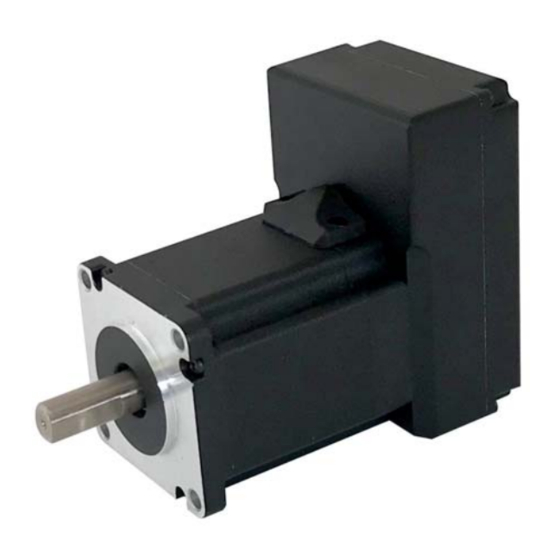
Page 80: Sv160E2 Outline Drawing
Figure T1.1 SV160E2 Outline Drawing 1.4.2 SV160E2 Mounting The SV160E2 is not water tight. Its IP64 rating makes it acceptable for use in dusty environments, environ- ments with condensation, and environments where the unit may be exposed to splashing water. -
Page 81: Power Connector
Figure T1.2 M12 Power Connector Pinout +DC Power and DC Common are used to power the SV160E2. The Ext. Brake Resistor pin is for an external regeneration resistor to limit power dissipation during deceleration. The Chassis GND pin should be used to ground the chassis of the motor if it is not ground through its mounting. -
Page 82: Power Wiring
1.6 Power Wiring The SV160E2 accepts 48 to 80 Vdc as its input power. AMCI strongly suggests using 16 AWG wire for the power connections. The MS-41 connector will accept up to 16 gauge wire and the CNGL-5M cordset is built with 16 gauge wire. -
Page 83: Compatible Connectors And Cordsets
1.7.3 Cable Shields Because they are low power signals, cabling from the sensor to the SV160E2 should be done using a twisted pair cable with an overall shield. The shield should be grounded at the end when the signal is generated, which is the sensor end. -
Page 84: Dc Input Wiring
Table T1.3 Pull Up Resistor Values for DC Inputs The logical states of the sensor and SV160E2 input will be reversed. The SV160E2 input is off when the sen- sor is active. You can set the logic state of the input when you configure the unit. -
Page 85: Sto Input Wiring
1.9 STO Input Wiring The SV160E2-STO uses Inputs 3 and 4 as the redundant STO inputs. These inputs must have 12 to 24 Vdc applied to them before the motor’s power stage is enabled. If you have an SV160E2-STO and are not using the STO functionality, then you must apply 12 to 24Vdc to both inputs to bypass the STO functionality. -
Page 86: Network Connectors
“auto-sense” ports that will automatically switch between 10baseT and 100baseT depend- ing on the network equipment they are attached to. The ports also have “auto switch” capability. This means that a standard cable can be used when connecting the SV160E2 to any device, including a personal computer. Pin 2: +Rx Pin 3: –Tx... -
Page 87: Ethernet/Ip Connections
1.13 Modbus TCP Connections The SV160E2 unit has two Ethernet ports with a built-in Ethernet switch connecting the two. Either port can be used to attach the unit to the network. The remaining port can be used to extend the network to another device if this reduces wiring costs. - Page 88 SV160E2 SV160E2 User Manual NSTALLING THE Notes ADVANCED MICRO CONTROLS INC.
-
Page 89: Protocol
IP address of an AMCI SV160E2. 2.1 Determine the Best Method for Setting the IP Address There are three methods for setting the IP address on an SV160E2. Table T2.1 below outlines the available methods and when you can use them. -
Page 90: Use The Embedded Web Server
The internal HTML pages should work with any browser. Once your web browser is running, enter the pres- ent IP address of the SV160E2 into the address bar. The default address is 192.168.0.50. The unit will respond with the following page. - Page 91 The Default Gateway setting is not optional! It must be set to a valid address on the chosen subnet. Because the Default Gateway is often not used in device level networks, if you do not have a required value for it, AMCI suggests setting the Default Gateway to the IP address of your host controller.
- Page 92 5) If the values are accepted, the following pages will be displayed while the data is being written to the unit. Wait for the pop up window to appear before cycling power to the SV160E2. Cycling power before this window appears may corrupt the non-volatile memory of the unit. The SV160E2 unit will also flash its Network Status LED red to indicate that power must be cycled.
-
Page 93: Use The Amci Net Configurator Utility
2.2c.2 Install the AMCI Net Configurator Utility Once downloaded, simply extract the program from the ZIP file and run the program to install the AMCI Net Configurator utility on your computer. The software installs as most products do, giving you the option to change the file locations before installing the utility. - Page 94 ET THE DDRESS AND ROTOCOL 2.2c Use the AMCI Net Configurator Utility (continued) 2.2c.5 Start the AMCI Net Configurator Utility Double click on the utility’s icon. A welcome screen similar to the one in figure T2.4 below will appear. Figure T2.4 Net Configurator Welcome Screen...
- Page 95 [Manual Connect] button and enter the IP address of the unit. Figure T2.5 Scan for SV160E2 If scanning for the SV160E2, click on the IP Address of the unit and click on the [Connect] button. The Net Configurator utility will connect to the unit.
- Page 96 Default Gateway to the IP address of your host controller. 2.2c.9 Set the Communications Protocol The factory default protocol for the SV160E2 is EtherNet/IP. In order to use the Modbus TCP or PROFINET protocols, simply click on the appropriate button.
-
Page 97: Task 3: Implicit Communications With An Eds
20 and above. Other systems will follow a similar pattern. Consult your controller’s documentation if you need additional information. Note: Use of an EDS file is completely optional. The SV160E2 can always be added to a system as a generic module. If you are using RSLogix 5000 version 19 and below, or RSLogix 500, adding the unit as a generic module is the only option available. -
Page 98: Install The Eds File
3) Click on the [Browse...] button and browse to the folder that contains the extracted EDS file you downloaded from the AMCI website. Select the EDS file and click on the [Open] button to return to the registration screen. Click on the [Next >] button to advance to the EDS file test screen. - Page 99 6) Click on the [Change icon...] button. In the window that opens, click on [Browse...] and browse to the folder that contains the extracted EDS and icon files you downloaded from the AMCI website. 7) Select the icon file (*.ico) associated with the device. Click on the [Open] button and then on [OK] to return to the Change Graphic Image screen.
-
Page 100: Host System Configuration
If the Ethernet port is built into processor, the only step you have to take before adding an AMCI SV160E2 is to create a new project with the correct processor or modify an existing project. Once this is done, the Ethernet port will automatically appear in the Project Tree. -
Page 101: Sv160E2 Properties Setup
If you are continuing from step 3.4, the resulting New Module screen is used to configure the network connec- tion between the SV160E2 and your controller. If you need to open the screen to perform this task at a later time, right click on the SV160E2 in the project tree and then select “Properties”... -
Page 102: Buffering The I/O Data
SV160E2 User Manual MPLICIT OMMUNICATIONS WITH AN 3.6 Buffering the I/O Data Input and output data is transferred asynchronously to the program scan. The input data tags should be buff- ered with Synchronous Copy File instructions to guarantee stable input data during the program scan. -
Page 103: Messaging
An Integer file to contain the data from the SV160E2. This file must be at least 10 words in length. An Integer file to contain the data sent to the SV160E2. This file must be at least 10 words in length. ... -
Page 104: Add The Message Instructions To Your Ladder Logic
Data Table Address (Received) field and press enter. 5) If the Message Instruction is being used to write data to the SV160E2, enter the integer file where the source data will be located in the Data Table Address (Send) field and press Enter. - Page 105 8) Double click in the Service field and select “Read Assembly” for a Message Instruction that is being used to read data from the SV160E2, or “Write Assemble” for a Message Instruction that is being used to send data to the SV160E2, and press Enter.
- Page 106 The figure below show a typical configuration for Message Instructions being used to write data to the SV160E2. Please note that the Data Table Address (Send) field may be different in your application. Figure T4.4 Write Message Instruction Setup Screen Click on the MultiHop tab on the top of the window.
-
Page 107: Troubleshooting
ESSAGING 4.4 Troubleshooting If you are unable to communicate with the SV160E2, the problem may be that the Ethernet port of your MicroLogix 1100 has not been configured. To check this: 1) Double click on Channel Configuration in the Project Tree and then select the Channel 1 tab. The fol- lowing window will open. - Page 108 /IP E SV160E2 User Manual THER XPLICIT ESSAGING Notes ADVANCED MICRO CONTROLS INC.
-
Page 109: Task 5: Modbus Tcp Configuration
If this is the case, you will define a mapping between your host controller’s addressing scheme and the zero based Modbus TCP addresses when you add the SV160E2 to your host controller. Refer to your host control- ler’s documentation for information on how to accomplish this. -
Page 110: Amci Modbus Tcp Memory Layout
5.3 AMCI Modbus TCP Memory Layout The SV160E2 has a starting Input Register address of 0 and a starting Output Register address of 1024. Input Registers hold the data from the driver while Output Registers hold the data to be written to the unit. Figure T5.1 shows how an SV160E2 is mapped to the Modbus data reference. -
Page 111: Supported Modbus Functions
Table T5.1 Supported Modbus Functions Table T5.1 above lists all of the Modbus functions supported by an SV160E2. AMCI supports all of these functions so that you can control the unit as you see fit. However, if you are looking for the easiest way to interface with your unit, then you only need to use the Read/Write Registers function, which is function code Each SV160E2 buffers the data that is sent to it over the network. - Page 112 TCP C SV160E2 User Manual ODBUS ONFIGURATION Notes ADVANCED MICRO CONTROLS INC.
-
Page 113: Task 6: Profinet Network Configuration
Catalog. 6.3 Configure the PROFINET Network A CPU must be added to the project and the PROFINET network must be configured before the SV160E2 can be added to the system. Refer to Siemens documentation for information on configuring the PROFINET network to suit your applica- tion. -
Page 114: Add The Sv160E2 To The Profinet Network
ETWORK ONFIGURATION 6.4 Add the SV160E2 to the PROFINET Network 1) With the project open in Project View, double click on “Device & Networks” in the project tree. 2) If need be, click on the “Hardware Catalog” vertical tab to open the Hardware Catalog. - Page 115 6) Under the “ PROFINET interface [x1]” heading, select “Ethernet addresses”. Under the IP protocol section, set the desired IP address and subnet mask for the SV160E2. Figure T6.3 Networked Driver IP Addressing 20 Gear Drive, Plymouth Ind. Park, Terryville, CT 06786...
-
Page 116: Configure The Sv160E2
1) Continuing with the Inspector Window, click on the “Module parameters” heading. The display will change to show all of the parameters of the SV160E2. These configuration parameters are written down to the SV160E2 whenever it connects to the network. -
Page 117: Set The I/O Configuration
6.6 Set the I/O Configuration The SV160E2 units require 10 Input Words (20 Input Bytes) and 10 Output Words (20 Output Bytes). All required Input and Output Bytes are defined by the GSDML file and divided into suitable modules. These set- tings are shown in the Table T6.1. -
Page 118: Set The Sv160E2 Device Name
4) Confirm that the “PROFINET device name:” at the top of the screen is correct. 5) Click on the [Assign name] button to write the device name to the SV160E2. The “Online status information:” table at the bottom of the screen will show that the name was successfully assigned to the MAC address of the SV160E2. -
Page 119: Mrp Installations
ONFIGURATION MRP Installations At this point, the SV160E2 is configured and ready to use. If you are using the unit in a redundant, ring based, network that uses the Media Redundancy Protocol (MRP), continue with the following instructions. Media Redundancy Protocol (MRP) installations require that the SV160E2 be installed in a ring topology. - Page 120 ADVANCED MICRO CONTROLS INC. LEADERS IN ADVANCED CONTROL PRODUCTS...
Need help?
Do you have a question about the SV160E2 and is the answer not in the manual?
Questions and answers