Table of Contents
Advertisement
Quick Links
ADVANCED
MICRO CONTROLS INC.
Manual #: 940-0S064
Table of Contents
General Information .................. 2
Introducing the SD17060B ........ 3
Specifications ............................ 6
Installations ............................... 7
Mounting the SD17060B ........... 8
Switch Settings .......................... 9
Connecting Your Controller ..... 10
Connecting Your Motor ............. 12
Indicator LED's .......................... 13
Verifying System Setup ............ 14
Troubleshooting ........................ 16
SD17060B Drivers ..................... 18
SD17060B-24 Drivers ................ 19
®
Advertisement
Table of Contents

Subscribe to Our Youtube Channel
Related Manuals for AMCI SD17060B


Summary of Contents for AMCI SD17060B
-
Page 1: Table Of Contents
ADVANCED MICRO CONTROLS INC. Manual #: 940-0S064 Table of Contents General Information ....2 Introducing the SD17060B ..3 Specifications ......6 UL/CUL Recognized Installations ....... 7 Mounting the SD17060B ... 8 Switch Settings ......9 Connecting Your Controller ..10 Connecting Your Motor ..... -
Page 2: General Information
Please direct all comments to: Technical Documentation, AMCI, 20 Gear Drive, Terryville CT 06786, or fax us at (860) 584-1973. You can also e-mail your questions and comments to techsupport@amci.com... -
Page 3: Introducing The Sd17060B
SD17060B drivers manufactured during December of 2008. This manual also applies to all SD17060B-03 and SD17060B-25 drivers. You will be able to determine the date of manufacture from the serial number on the driver. Serial numbers for all AMCI drivers are formed from a date code and sequential number. The serial number format is shown below. - Page 4 On the SD17060B and SD17060B-25 units, the Fault Output will be off if the driver is disabled on power up. On the SD17060B-03, if the driver is disabled on power up, the Fault Output will be on and stay on until the drive is enabled.
- Page 5 Greater efficiency and a thinner front panel means you can space the drivers closer together in an enclo- sure. The Disable Input on the SD17060B can be used to reset the driver. The SD17060 could only be reset by cycling power to it. ...
-
Page 6: Specifications
Current is restored to full value on next Weight pulse. 2.4 lbs. (1.1 kg.) Resolution SD17060B: Inputs Switch selectable to 200, 400, 1,000, 2,000, Electrical Characteristics for all Inputs: ....5,000, 10,000, 12,800, 18,000 20,000, 21,600, Differential. 1500 Vac/dc opto-isolated. Can be 25,000, 25,400, 25,600, 36,000, 50,000, or wired as single ended inputs. -
Page 7: Ul/Cul Recognized Installations
The SD17060B does not provide overspeed protection. The SD17060B shall be used in pollution degree 1 or 2 environments. If the SD17060B is mounted in an enclosure, this enclosure must meet these requirements. All wiring to the SD17060B shall be R/C (AVLV2), minimum rating of 80°C, 300V, except secondary low-voltage circuit wiring. -
Page 8: Mounting The Sd17060B
SD17060B enclosure and is a sufficient grounding point for most applications. When mounted the SD17060B on a surface that is electrically conductive and grounded, you should also take steps to ensure that the two are electrically bonded together. If necessary, remove paint for the bolt mounting surfaces of the panel to ensure adequate electrical bonding. -
Page 9: Switch Settings
SWITCH SETTINGS The SD17060B is configured by DIP switches on the top of the driver. The factory default setting has all switches in their off (0) position except for SB2-1. (CurrentLoop Gain = 1) All switch setting are latched. You must cycle power to the driver before changes take effect. -
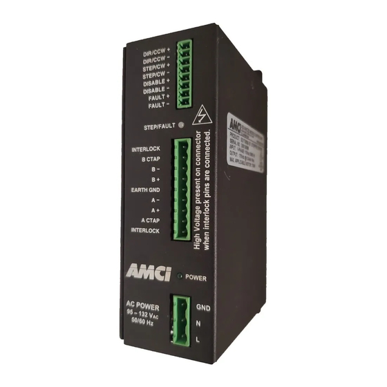
Page 10: Connecting Your Controller
CONNECTING YOUR CONTROLLER I/O Connector The I/O connector on the SD17060B accepts inputs from your indexer DIR/CCW as well as the Disable Input and Fault Output. DIR/CCW Indexer Inputs STEP/CW All SD17060B-03 drivers and SD17060B drivers sold after Decem- STEP/CW... - Page 11 A resistor may be needed to limit the current through the Fault Output. The value, and power rating of the resistor is dependent on the value of Vdc, the voltage drop across the input, and the current requirements of the input. 20 Gear Drive, Plymouth Ind. Park, Terryville, CT 06786 Tel: (860) 585-1254 Fax: (860) 584-1973 http://www.amci.com...
-
Page 12: Connecting Your Motor
CONNECTING YOUR MOTOR Compatible Motors The SD17060B will work with many different motors, including those not sold by AMCI. This section assumes that you have already chosen your motor and you are looking for wiring information. No wire colors are given because there is no single industry wide color coding standard for stepper motor wires. You must refer back to your motor data sheets for this information. -
Page 13: Power Connector And Indicator Led's
POWER CONNECTOR AND INDICATOR LED’s Power Connector The SD17060B operates on 115Vac. If 230Vac is the only power available, consider using one of the 230Vac drivers available from AMCI. Information on these drivers can be found on our website, http://www.amci.com. If this is not an option, a step-down transformer must be installed to power the SD17060B. -
Page 14: Verifying System Setup
If need be, adjust the Current Loop Gain settings up or down depending on your application. In some cases, the Current Loop Gain can be set to its AutoMode setting and the SD17060B will automati- cally determine the proper gain on every power up or reset. This procedure is done in under two seconds. - Page 15 8) If you are using the Fault Output, verify that it is On (conducting). Remove power from the SD17060B, disconnect the motor, and re-apply power. The STEP/FAULT LED should be red and the Fault Output should be off (not conducting).
-
Page 16: Troubleshooting
Symptom Solution My indexer/PLC reports a fault Your logic may be reversed. On the SD17060B, the Fault Output is on (conducts current) when the driver is working correctly and turns off (stops from the SD17060B when every- current flow) when there is a fault with the driver. Therefore, losing power thing seems fine. - Page 17 As noted above, sometimes a problem that appears to be with the motor is actually a problem with the indexer. The SD17060B has a Self-Test feature that allows you to verify motor opera- tion without an indexer. With power applied to the driver, toggle the SB4-1 switch. The motor will begin to rotate clockwise at 60 RPM.
-
Page 18: Using Older Sd17060B Drivers
24Vdc input signals. You will be able to determine the date of manufacture from the serial number on the driver. Serial numbers for all AMCI drivers are formed from a date code and sequential number. The serial number format is shown below. -
Page 19: Using Older Sd17060B-24 Drivers
This appendix applies to all SD17060B-24 drivers. The SD17060B-24 has internal current limiting resistors on its inputs and can only be used in 24Vdc systems. The SD17060B-24 was phased out of production in December of 2008 and replaced by the redesigned SD17060B. - Page 20 ADVANCED MICRO CONTROLS INC. LEADERS IN ADVANCED CONTROL PRODUCTS...
Need help?
Do you have a question about the SD17060B and is the answer not in the manual?
Questions and answers