Table of Contents
Advertisement
Quick Links
Advertisement
Table of Contents

Related Manuals for Helmholz PN/CAN gateway PROFINET/CANopen Master


Summary of Contents for Helmholz PN/CAN gateway PROFINET/CANopen Master
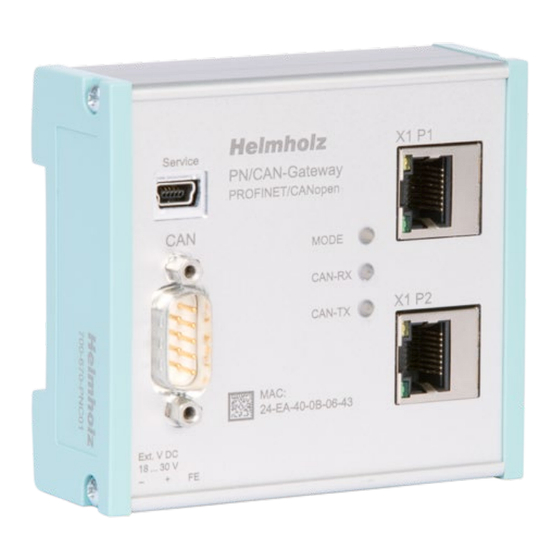
- Page 1 Version 4 / 18.03.2020 | for firmware V1.06 and above Link to newest version of manual Helmholz GmbH & Co. KG | Hannberger Weg 2 | D-91091 Großenseebach | Germany Phone +49 9135 7380-0 | Fax +49 9135 7380-110 | info@helmholz.de | www.helmholz.com...
- Page 2 Helmholz GmbH & Co. KG. All rights reserved in the event of the granting of a patent or the registration of a utility model. To download the latest version of this manual, please visit our website at www.helmholz.de. We welcome all ideas and suggestions.
-
Page 3: Table Of Contents
Contents General ......................5 Target audience for this manual....................5 Safety instructions ........................5 Note symbols and signal words ....................6 Intended use ........................... 7 Improper use ........................... 7 Liability ............................ 8 1.6.1 Disclaimer of liability ......................8 1.6.2 Warranty ..........................8 Recycling / WEEE ........................ - Page 4 5.3.2 CANopen functions ......................17 5.3.3 Network management ....................... 18 Setup and use ....................20 Install GSDML file ........................20 Configuring gateway ......................20 6.2.1 Configure gateway master ....................22 6.2.2 Add and configure CANopen device .................. 23 6.2.3 Minimum requirements of a CANopen slave ..............24 6.2.4 Configure PDOs .........................
-
Page 5: General
General This operating manual applies only to devices, assemblies, software, and services of Helmholz GmbH & Co. KG. 1.1 Target audience for this manual This description is only intended for trained personnel qualified in control and automation engineering who are familiar with the applicable national standards. For installation, commissioning, and operation of the components, compliance with the instructions and explanations in this operating manual is essential. -
Page 6: Note Symbols And Signal Words
1.3 Note symbols and signal words If the hazard warning is ignored, there is an imminent danger to life and health of people from electrical voltage. If the hazard warning is ignored, there is a probable danger to life and health of people from electrical voltage. -
Page 7: Intended Use
Modifications to hardware or software configurations which are beyond the documented options are not permitted and nullify the liability of Helmholz GmbH & Co. KG. The PN/CAN gateway may not be used as the only means for preventing hazardous situations on machinery and systems. -
Page 8: Liability
Helmholz GmbH & CO. KG is not liable for damage caused by software that is running on the user’s equipment which compromises, damages, or infects additional equipment or processes through the remote maintenance connection and which triggers or permits unwanted data transfer. -
Page 9: Recycling / Weee
1.7 Recycling / WEEE The company Helmholz GmbH & Co. KG is registered as a manufacturer with the HELMHOLZ brand and the device type "Small devices of information and telecommunications technology for exclusive use in households other than private households" as well as the following registration data: Helmholz GmbH &... -
Page 10: System Overview
System overview 2.1 General/area of application The PN/CAN gateway integrates a CANopen network into a PROFINET network. It is a full-fledged CANopen master and enables the incorporation of the process and service data of CANopen slave devices into the IO area of a PROFINET CPU. 2.2 Properties des PN/CAN-Gateways CANopen The PN/CAN gateway, PROFINET/CANopen Master has the following properties: •... -
Page 11: Installation
Installation 3.1 Access restriction The modules are open operating equipment and must only be installed in electrical equipment rooms, cabinets, or housings. Access to the electrical equipment rooms, cabinets, or housings must only be possible using a tool or key, and access should only be granted to trained or authorized personnel. 3.2 Electrical installation Observe the regional safety regulations. -
Page 12: Installation Position
Installation must be carried out according to VDE 0100/IEC 364 and performed in accordance with applicable national standards. The PN/CAN gateway has protection rating IP20. If a higher protection rating is required, the system must be installed in a housing or control cabinet. In order to ensure safe operation, the ambient temperature must not exceed 60 °C. -
Page 13: Setup And Wiring
Setup and wiring 4.1 EMC/safety/shielding The PN/CAN gateway complies with EU Directive 2004/108/EC (“Electromagnetic Compatibility”). One effective way to protect against disturbances caused by electromagnetic interference is to shield electric cables, wires, and components. When setting up the system and routing the required cables, make sure to fully comply with all standards, regulations, and rules regarding shielding. -
Page 14: Wiring Of The Pn/Can Gateway
4.2 Wiring of the PN/CAN gateway 4.2.1 Voltage supply The PN/CAN gateway is supplied with 24 V DC voltage via the 3-pin power supply plug. 4.2.2 CAN bus connection CAN bus D-sub connector CAN low CAN GND CAN high PN/CAN gateway contains no terminating resistor for the CAN bus! 4.2.3 PROFINET connection Signal RJ45 plug PROFINET... -
Page 15: Can Bus
5.2 CAN bus plug Helmholz offers a comprehensive range of CAN bus connectors that can be used with the PN/CAN gateway. All Helmholz CAN bus connectors come with a terminating resistor that can be switched on and off. -
Page 16: The Canopen Protocol
5.3 The CANopen protocol The CANopen® protocol is a layer 7 (application layer) protocol based on the CAN bus. CAN bus layers 1 and 2 (physical layer and data link layer) are used by the CAN bus unchanged. The service elements provided by the application layer make it possible to implement applications that are distributed throughout the network. -
Page 17: Canopen Functions
5.3.2 CANopen functions The CANopen functions are subdivided into the following basic types: • SDO read and SDO write operations • PDO read and PDO write operations • Network management • Emergency messages The function code is stored in the upper four bits of the CAN identifier, which, together with the node ID, forms the communication object identifier, or COB-ID. -
Page 18: Network Management
5.3.3 Network management Network status (NMT states): Each CANopen device can have various system states. After the device is switched on, an internal system initialization is carried out (hardware initialization, RAM test, setup of the basic objects). After successful initialization, a boot up frame [COB-ID: 700 + node ID / data (1 byte): 00 After this, the device is ready for operation and in the Pre-Operational state. - Page 19 Node guarding: Node guarding means that the master monitors the CANopen slaves with cyclically transmitted frames. Each CANopen slave must respond to the node guarding frame with a status frame. [COB-ID: 700 + node ID / data: 1 byte with slave status] Life guarding: Life guarding means that each CANopen slave will monitor to make sure that the master continuously carries out the started node guarding within specific time limits.
-
Page 20: Setup And Use
6.2 Configuring gateway The PN/CAN gateway can be found in the hardware catalogue under " Other field devices PROFINET IO Gateway Helmholz PN/CAN gateways". Add the "PN/CAN gateway CANopen" to the project and connect it with your PROFINET network. - Page 21 By calling up the object properties, the PN/CAN gateway should be assigned a unique PROFINET name and the IP address be checked for plausibility. The name of the configured device must later be assigned to the physical device (see Ch. 6.3). PN/CAN gateway, PROFINET/CANopen Master | Version 4 | 18.03.2020...
-
Page 22: Configure Gateway Master
6.2.1 Configure gateway master The first slot entry "Parameter" contains the module parameters for the behavior of the CANopen master. CAN bit rate: 10, 50, 100, 125, 250, 500, 800 Kbps and 1 Mbps are available as bit rates. CAN master node ID: Node ID under which the PN/CAN gateway at the CAN bus is active. In some applications, a SYNC frame is necessary for operation. -
Page 23: Add And Configure Canopen Device
Note: If the PLC is restarted and the CAN bus is not stopped at stop, the CAN bus is stopped at the PLC start of the CAN bus and reinitialized. In the case of master reset, NMT stop instead of NMT PreOp.: When the master carries out a reset (due to PLC stop, interruption of connection or user request), an "NMT Pre-Operational"... -
Page 24: Minimum Requirements Of A Canopen Slave
CANopen profile The profile of a slave is found in the lower 2 bytes of the SDO 1000. If the profile is indicated in the configuration and the Check CANopen profile option has been switched on, then the device at the CAN bus must also have this profile for initialization. -
Page 25: Configure Pdos
6.2.4 Configure PDOs TPDOs (transmit process data objects) are data sent by the CANopen slave to the PLC (input data from PLC view). RPDOs (receive process data objects) are sent by the PLC to the CANopen slave (output data from PLC view). The data size of the PDOs depends upon the data found in the PDO (PDO mapping) and can range between one and 8 bytes. -
Page 26: Cob-Ids Of The Pdos
PDO TTYPE: Transmission type of the PDO as defined by the CANopen standard. Only the TTYPEs 0 – 240 (synchronous), 254, and 255 (event-driven) are supported. The TTYPEs 241 to 253 should not be set. When the TTYPEs 0 – 240 are used, the SYNC frame should be configured in the master configuration (see Ch. -
Page 27: Maximum Extension Of The Pn/Can Gateway Configuration
6.2.6 Maximum extension of the PN/CAN gateway configuration The maximum extension of a project configuration is limited by the following parameters: • A maximum of 126 CANopen Slaves can be created • A CANopen slave can have a maximum of 16 RPDOs and 16 TPDOs •... -
Page 28: Assign The Profinet Device-Name
PLC and configured. When the configuration has run correctly, the blue "Mode" LED should blink. To set the PROFINET name, the Helmholz IPSet Tool can also be used, which can be downloaded free of charge from the Helmholz website. Scan the following QR code to download IPSet Tool: PN/CAN gateway, PROFINET/CANopen Master | Version 4 | 18.03.2020... -
Page 29: Programming In The Plc
Programming in the PLC 7.1 Master control No handling blocks for operation are required in the PLC. The control and status query of the PN/CAN gateway can be carried out directly via the I/O map. For more complex applications, sample programs for the TIA Portal are available on request. -
Page 30: Master Status
be reset. The desired NMT state (1 or 2 in the NMT State Control) can subsequently be requested and the PN/CAN gateway initializes the bus again. 7.1.2 Master status The master status consists of 4 input bytes. Byte/bit Gateway In 0 configured SYNC User reset... - Page 31 No CAN connection: There is no recognizable CAN network (no participants, open termination resistors) CAN RX-FIFO Overflow: Overflow of the Rx-FIFO in the CAN controller CAN bus error (Rx/Tx): The bit indicates if the CAN Rx or Tx error counter is not equal to 0. CAN bus offline: The CAN controller is offline PN/CAN gateway, PROFINET/CANopen Master | Version 4 | 18.03.2020...
-
Page 32: Canopen Device
7.2 CANopen device 3 bytes of input data with the status information of the slave exist for each configured CANopen slave and one output byte for slave control. 7.2.1 CANopen Device Status Byte/bit Restart of Slave trans- Incorrect Resend CANopen Slave not Slave In 0... -
Page 33: Canopen Device Control
7.2.2 CANopen Device Control Byte/bit Restart Resend all Out 0 Slave RPDOs Restart Slave: The CANopen slave is restarted and initialized. Depending upon the global parameter "No communication-Transmit reset" (see Ch. 6.2.2), an NMT reset or only an NMT Pre-Operational command will initially be transmitted to the slave device before it is reinitialized. -
Page 34: Sdo Communication
7.4 SDO communication SDO communication with the slaves can take place following the initialization phase of the PN/CAN gateway both in the Pre-Operational (NMT state = 1) and Operational (NMT state = 2). Only one SDO job can be carried out at a time. Both the reading and writing of SDOs is possible. Byte/bit SDO size: Job type:... -
Page 35: Sdo Transmission Example
7.4.1 SDO transmission example In hardware configuration represented above, the SDO communication area is configured to the IO addresses 110 to 118: EB 110: SDO status ED 111: SDO receive data ED 115: SDO abort code AB 110: SDO control AB 111: Node ID of the SDO slave AW 112: SDO index AB 114: SDO sub-index... -
Page 36: Emergency Messages
7.5 Emergency messages Emergency messages from the slaves are always received by the PN/CAN gateway and made available to the PLC. The PN/CAN gateway does not itself react actively to the emergency messages. The messages must be evaluated by the application program. Byte/bit In 0 Emergency message indication... -
Page 37: Layer Setting Service (Lss)
7.6 Layer Setting Service (LSS) The PN/CAN makes it possible to carry out LSS functions on the CAN bus (as of firmware version 1.04). With the LSS protocol, the node ID and the Baud rate of CANopen slave participants, among other things, can be set, insofar as this support the LSS protocol. - Page 38 In order to carry out the LSS functions on the CAN bus, these must be programmed in the PLC. To this purpose, the LSS module makes available the following command interface in the IO map. LSS control: Byte / Bit LSS control Set LSS Baud rate: Transmit...
-
Page 39: Profinet Diagnosis Alarm
7.7 PROFINET diagnosis alarm The PN/CAN gateway supports the following diagnosis alarms: Configuration error SDO 0x1001 in the same is no longer equal to 0 * Configuration error at the slave (e.g. same PDO numbers) Alarm for master transition due to missing mandatory slave * Slave has node guarding or heartbeat failure * CAN bus error (RX overflow, bus error, bus off event) * * these alarms can be locked through configuration (in progress) -
Page 40: Led-Based Diagnosis
LED-based diagnosis MODE No power supply or device defective PN/CAN gateway is correctly configured via PROFINET & Blue on all CANopen slaves are in Operational state PN/CAN gateway is correctly configured via PROFINET & Flashing blue at least one CANopen slave is in Pre-Operational or Stop state Red on No connection with PROFINET controller (PLC) Flashing red... -
Page 41: Profinet Certificate
PROFINET Certificate PN/CAN gateway, PROFINET/CANopen Master | Version 4 | 18.03.2020... -
Page 42: Technical Data
10 Technical data Order no. 700-670-PNC01 Name PN/CAN gateway, PROFINET/CANopen Master PROFINET interface Protocol PROFINET IO device as defined in IEC 61158-6-10 Transmission rate 100 Mbps full duplex I/O image size 1440 bytes Connection 2x RJ45, integrated switch PROFINET Conformance Class C, Media redundancy (MRP client), Features Automatic addressing,...
Need help?
Do you have a question about the PN/CAN gateway PROFINET/CANopen Master and is the answer not in the manual?
Questions and answers