Table of Contents
Advertisement
Quick Links
Advertisement
Table of Contents

Related Manuals for Helmholz 700-671-PNC01


Summary of Contents for Helmholz 700-671-PNC01
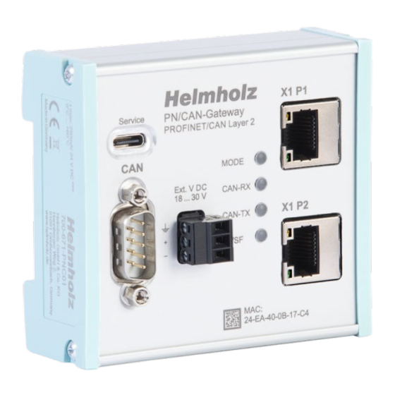
- Page 1 Quickstart Guide Version PN/CAN Gateway CAN Layer 2 Order number: 700-671-PNC01 Helmholz GmbH & Co. KG | Hannberger Weg 2 | 91091 Großenseebach | Germany 06.10.2023 Phone +49 9135 7380-0 | Fax +49 9135 7380-110 | info@helmholz.de | www.helmholz.de...
-
Page 2: Table Of Contents
Content Safety instructions ....................3 Introduction ......................3 Function of PN/CAN Gateway CAN Layer 2 ............4 Connection ......................4 Power supply ..........................4 CAN-Bus ............................4 PROFINET ............................. 4 USB interface ..........................4 Download and Installation of GSDML file ............. 5 Install GSDML file in TIA Portal ...................... -
Page 3: Safety Instructions
This document explains the initial commissioning of the PN/CAN-Gateway CAN Layer 2. The latest version of the documentation can be found at www.helmholz.de or scan the QR code directly. Quickstart Guide PN/CAN-Gateway CAN Layer 2 | Version 4 | 06.10.2023... -
Page 4: Function Of Pn/Can Gateway Can Layer 2
4.2 CAN-Bus The CAN bus is connected to the "CAN" interface using a SUB-D CAN bus D-sub-connector plug (e.g. Helmholz CAN bus connector) to the "CAN" interface. The PN/CAN gateway does not contain a CAN terminating CAN Low resistor. If the PN/CAN gateway is connected to the end of a... -
Page 5: Download And Installation Of Gsdml File
5 Download and Installation of GSDML file The current GSDML file is available on the website www.helmholz.de. Go to the product page of the "PN/CAN Gateway CAN Layer 2" and then to the download area or follow the link stored in the QR code. There you can download the GSDML file of the "PN/CAN Gateway CAN Layer 2"... -
Page 6: Configuring The Pn/Can-Gateway
6 Configuring the PN/CAN-Gateway Add the "PN/CAN-Gateway L2 V1.04" to the project and connect it to your PROFINET network. By calling the properties a unique PROFINET name should be assigned to the PN/CAN gateway and the IP address should be checked for plausibility. The name of the configured device must be assigned to the physical device later (see Chap. -
Page 7: Adding Can Messages
6.2 Adding CAN messages The PN/CAN gateway layer 2 can send and receive CAN messages with 0 to 8 bytes of data and any CAN ID. For each expected CAN message and each CAN message to be sent, a module with the CAN identifier must be configured in the slots of the PN/CAN gateway. -
Page 8: Automatically Receiving Can Messages
6.2.1 Automatically receiving CAN messages In the case of the Automatic Receive of CAN messages, the data of the most recently received CAN message is always found in the input data. Each configured CAN message has a clear CAN identifier. If two receive objects with the same CAN identifier are being configured, that results in a configuration error. -
Page 9: Assign A Profinet Device Name To The Pn/Can Gateway
When the configuration has run correctly, the blue "Mode" LED should blink. To set the PROFINET name, the Helmholz “IPSet” Tool can also be used, which can be downloaded free of charge from the Helmholz website. Scan the following QR code to download “IPSet”... -
Page 10: Programming In The Plc
8 Programming in the PLC No handling blocks are required for operation of the PN/CAN gateway in the PLC. The control and status query of the PN/CAN gateway can be carried out directly via the I/O image. To start the example project, the value 3 must be written into the "Control" output word to switch to normal operation. -
Page 11: Led-Based Diagnosis
9 LED-based diagnosis MODE No power supply or device defective PN/CAN gateway is correctly configured via PROFINET Blue on Mode 3 – Transmission and receiving active PN/CAN gateway is correctly configured via PROFINET Flashing blue Mode is 0, 1, or 2 Red on No connection with PROFINET controller (PLC) Flashing red... -
Page 12: Technical Data
10 Technical data Order no. 700-671-PNC01 Name PN/CAN gateway, PROFINET/CAN Layer 2 Scope of delivery PN/CAN gateway with power plug Dimensions (D x W x H) 35,5 x 83,5 x 76 mm Weight Approx. 160 g PROFINET interface (X1) Number... - Page 13 We can send you the corresponding license conditions, including a copy of the complete license text together with the product. They are also provided in our download area of the respective products under www.helmholz.de. We also offer to send you or any third party the complete corresponding source text of the respective open-source software for an at-cost fee of 10.00 Euro as a...
Need help?
Do you have a question about the 700-671-PNC01 and is the answer not in the manual?
Questions and answers