Table of Contents
Advertisement
Advertisement
Table of Contents

Subscribe to Our Youtube Channel
Related Manuals for NCR 6625


Summary of Contents for NCR 6625
- Page 1 NCR 6625 ATMs Site Preparation B006-6663-A000 1207...
- Page 2 If this equipment does cause interference, which can be determined by turning the equipment off and on, the user is encouraged to consult an NCR service representative immediately.
-
Page 3: Table Of Contents
Table of Contents NCR 6625 ATM Site Preparation INTRODUCTION .......................1 How to Use This Site Preparation Bookset ..............2 Purpose and Audience ....................2 Site Compliance ......................2 Customer Responsibilities ....................3 Product Identification .....................4 PACKAGE DIMENSIONS....................5 Manoeuvring the ATM Into Position................6 ATM DIMENSIONS......................7 Standard Sleeve Without Collar ..................8... - Page 4 Advert Collar......................26 Lowered Height Collar.....................27 SERVICE ACCESS PANELS AND FACIA APERTURE ..........28 HOLE IN THE WALL ......................29 NCR Optimum Height ....................29 Lowered Heights......................30 Centre for Accessible Environments in the UK (CAE) ...........30 Department of Justice Standard for Accessible Design (ADA).......30 Canadian Standards Association (CSA) ..............30...
-
Page 5: Introduction
NCR 6625 ATM Site Preparation Table of Contents NCR 6625 ATM Site Preparation INTRODUCTION The NCR 6625 Automated Teller Machine (ATM) may be installed through any suitable exterior wall or vestibule location. B006-6663-A000... -
Page 6: How To Use This Site Preparation Bookset
How to Use This Site Preparation Bookset The site preparation is part of the NCR 6625 Site Preparation Bookset. It acts both as a specifications book, and also as a gateway to the other books in the bookset, which are:... -
Page 7: Customer Responsibilities
NCR will not be liable in respect of any comment, suggestion or advice given by its staff or in respect of any failure to give advice. -
Page 8: Product Identification
Product Identification The product is identified by a class type number, 6625, and a 4 digit model number, which is printed on a label fixed inside the top cabinet of the ATM. The serial number is unique to each ATM. The tracer number is used to identify where the ATM was built. Please quote all of the serial and tracer numbers, including the prefix, when making reference to the ATM. -
Page 9: Package Dimensions
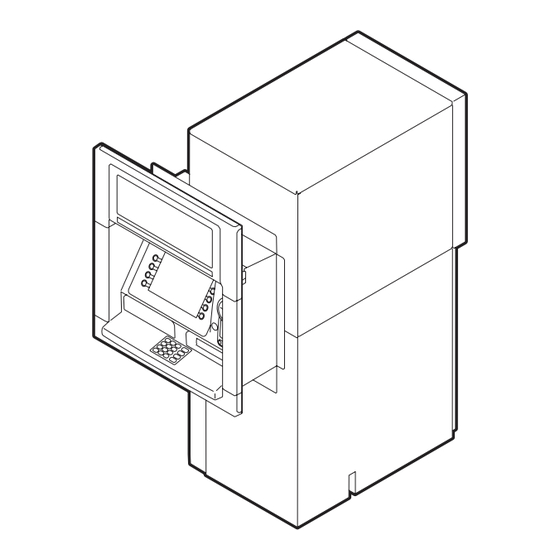
NCR 6625 ATM Site Preparation PACKAGE DIMENSIONS The dimensions of a packaged and unpackaged ATM are shown in the following illustration. 977 mm 1435 mm (38.5 in.) (56.5 in.) 1836 mm (72.3 in.) 1405 mm 957 mm (55.3 in.) (37.7 in.) -
Page 10: Manoeuvring The Atm Into Position
NCR 6625 ATM Site Preparation Manoeuvring the ATM Into Position Ensure that doorways and corridors leading to your point of installation are wide enough to allow the package to pass through, or make arrangements to unpack the ATM in an area with sufficient access and then move it to the installation site. -
Page 11: Atm Dimensions
NCR 6625 ATM Site Preparation ATM DIMENSIONS The following illustrations show dimensions for ATMs configured with CEN Grade L, CEN Grade I, CEN Grade III, CEN Grade IV Spanish Certified and UL 291 Level 1 security enclosures. Note: Cables enter the ATM through the hole in the base of the ATM security enclosure. -
Page 12: Standard Sleeve Without Collar
NCR 6625 ATM Site Preparation Standard Sleeve Without Collar UL Security Enclosure The illustration below shows the dimensions for a standard sleeve ATM configured with a UL security enclosure. It shows the sleeve before a collar has been fitted. 747 mm (29.4 in.) -
Page 13: Cen Security Enclosure
NCR 6625 ATM Site Preparation CEN Security Enclosure The illustration below shows the dimensions for a standard sleeve ATM configured with a CEN Grade I, CEN Grade L, CEN Grade III or CEN Grade IV Spanish Certified security enclosure. It shows the sleeve before a collar has been fitted. -
Page 14: Short Sleeve Without Collar
NCR 6625 ATM Site Preparation Short Sleeve Without Collar UL Security Enclosure The illustration below shows the dimensions for a short sleeve ATM configured with a UL security enclosure. It shows the sleeve before a collar has been fitted. 747 mm (29.4 in.) -
Page 15: Cen Security Enclosure
NCR 6625 ATM Site Preparation CEN Security Enclosure The illustration below shows the dimensions for a short sleeve ATM configured with a CEN Grade I, CEN Grade L, CEN Grade III or CEN Grade IV Spanish Certified security enclosure. It shows the sleeve before a collar has been fitted. -
Page 16: Collar Dimensions
NCR 6625 ATM Site Preparation Collar Dimensions Standard Collar The illustration below shows the dimensions for an ATM configured with a standard collar. 40 mm (1.57 in.) 75 mm 727 mm 64 mm (2.95 in.) (28.60 in.) (2.52 in.) 37.5 mm (1.48 in.) -
Page 17: Advert Collar
NCR 6625 ATM Site Preparation Advert Collar The illustration below shows the dimensions for an ATM configured with an advert collar. 40 mm 75 mm (1.57 in.) (2.95 in.) 278 mm 727 mm 37.5 mm (10.9 in.) (28.60 in.) (1.48 in.) 839 mm (33.0 in.) -
Page 18: Lowered Height Collar
NCR 6625 ATM Site Preparation Lowered Height Collar The illustration below shows the dimensions for an ATM configured with a lowered height collar. 40 mm 75 mm (1.57 in.) (2.95 in.) 84 mm 727 mm 37.5 mm (3.31 in.) (28.60 in.) (1.48 in.) -
Page 19: Access For All
NCR 6625 ATM Site Preparation ACCESS FOR ALL The ATM has been designed to meet the height and reach requirements of both able- bodied and disabled, excluding the visually impaired. For wheelchair users, the ATM offers optimised parallel approach, providing easy access, security and private space if installed according to the specifications detailed in this document. - Page 20 NCR 6625 ATM Site Preparation front B006-6663-A000...
-
Page 21: Topmost Viewable Facia Item
NCR 6625 ATM Site Preparation Topmost Viewable Facia Item The following illustrations show the projected angle from the front of the standard or advert collar and the lowered height collar to the topmost viewable facia item. 381 mm 381 mm (15 in.) Touchscreen... -
Page 22: Facia Item Locations For Voice Guidance
NCR 6625 ATM Site Preparation Facia Item Locations for Voice Guidance Facia Item Distance from No. 5 Key Clock Face Position 306 mm 305 mm (12.0 in.) Display - Top left-hand FDK (12.0 in.) 333 mm 381 mm (15.0 in.) Display - Top left-hand FDK (13.1 in.) -
Page 23: Wheelchair Clearance
NCR 6625 ATM Site Preparation Wheelchair Clearance The following illustration shows the clearance required for wheelchair approach and its turning circle. 1524 mm (60.0 in.) 1524 mm (60.0 in.) B006-6663-A000... -
Page 24: Installation And Service Clearances
NCR 6625 ATM Site Preparation INSTALLATION AND SERVICE CLEARANCES Important Notice to Users If it is likely that the ATM will be upgraded with new modules as they become available, you should use the optimum clearances. Note: Installing the ATM in the minimum servicing areas may impact servicing and/or upgrading times. -
Page 25: Optimum Clearances
NCR 6625 ATM Site Preparation Optimum Clearances Standard Sleeve The illustration below shows the optimum clearance dimensions for an ATM configured with a UL, or CEN, security enclosure and standard sleeve. 1474 mm (58.0 in.) 320 mm (12.6 in.) 1460 mm Module (57.5 in.) -
Page 26: Short Sleeve
NCR 6625 ATM Site Preparation Short Sleeve The illustration below shows the optimum clearance dimensions for an ATM configured with a UL, or CEN, security enclosure and short sleeve. 1474 mm (58.0 in.) 320 mm (12.6 in.) 1210 mm (47.6 in.) -
Page 27: Optimum Distance Between Two Installations
NCR 6625 ATM Site Preparation Optimum Distance Between Two Installations The optimum distance between the security enclosures of two ATMs, installed side by side, is 460 mm (18.1 in.). 2487 mm (97.9 in.) See Note 1 460 mm 460 mm 460 mm (18.1 in.) -
Page 28: Minimum Clearances
NCR 6625 ATM Site Preparation Minimum Clearances The following illustrations show the minimum areas required for installing and servicing the ATM. The illustration below shows the minimum clearance dimensions for an ATM configured with a UL, or CEN, security enclosure with standard or short sleeve. -
Page 29: Minimum Distance Between Two Installations
NCR 6625 ATM Site Preparation Minimum Distance Between Two Installations The minimum distance between two ATMs, installed side by side between the security enclosures, is 380 mm (15.0 in.). 2167 mm (85.3 in.) 380 mm 380 mm 300 mm (15.0 in.) (15.0 in.) -
Page 30: Exterior Wall Clearances
NCR 6625 ATM Site Preparation Exterior Wall Clearances The illustrations below show the minimum clear wall area required around the collar for installing and servicing the ATM. Standard Collar 10 mm (0.4 in.) 45 mm (1.8 in.) 30 mm 30 mm (1.2 in.) -
Page 31: Lowered Height Collar
NCR 6625 ATM Site Preparation Lowered Height Collar 100 mm (3.9 in.) 45 mm (1.8 in.) 30 mm 30 mm (1.2 in.) (1.2 in.) B006-6663-A000... -
Page 32: Service Access Panels And Facia Aperture
NCR 6625 ATM Site Preparation SERVICE ACCESS PANELS AND FACIA APERTURE For installations where there is enough room to stand at either side of the ATM, there are two service access panels on the top-box, one at either side, as shown below. The panels can be removed to allow easier access to the facia, keyboard and shutter areas. -
Page 33: Hole In The Wall
NCR 6625 ATM Site Preparation HOLE IN THE WALL The wall and floor need to be smooth and even as the collar has a tolerance of +/- 4 mm (0.2 in. (+/- 0.5°)) at the top and bottom, with 0 mm (0.0 in. (0°)) at its centre. This is shown in the following illustration. -
Page 34: Lowered Heights
NCR 6625 ATM Site Preparation Lowered Heights The following installation heights have been designed to meet the regulations listed below and therefore meet the requirements of both able-bodied and disabled people. Centre for Accessible Environments in the UK (CAE) To ensure maximum user accommodation relative to the UK Design Guidelines “Access to ATMs”, published by the Centre for Accessible Environments in the UK (CAE), the... -
Page 35: Australian Bankers' Association
NCR 6625 ATM Site Preparation Australian Bankers’ Association To comply with the Australian Bankers’ Association Industry Standard Automated Teller Machine (ATM), the ATM must be installed to ensure that the lowest consumer interface element is no less than 750 mm (29.5 in.) and the highest consumer interface element is no higher than 1200 mm (47.2 in.) from sidewalk level. -
Page 36: Installation Categories
NCR 6625 ATM Site Preparation Installation Categories Depending on the size of the hole that was cut for the previous installation, the 6625 ATM can be installed through a new hole, an existing Personas 84 hole, or an existing Personas 87 hole in the wall. -
Page 37: Installing Through A New Hole
NCR 6625 ATM Site Preparation INSTALLING THROUGH A NEW HOLE New Hole Installation at Lowered Height It is the responsibility of the owning institution to ensure that the heights from the sidewalk level to the facia items comply with any local regulations. For more information on the installation heights and regulations refer to the earlier section “Lowered Heights”... - Page 38 NCR 6625 ATM Site Preparation Note 1: The actual height of the plinth depends upon the difference in height between the sidewalk and the interior floor. If, as the illustration shows, there is no difference, then the plinth must have the height that is specified in the table above.
-
Page 39: New Hole Installation At Optimum Height
It is the responsibility of the owning institution to ensure that the heights from the sidewalk level to the facia items comply with any local regulations. Where no such regulations exist, the ATM can be installed at the NCR optimum height, as shown in the following illustration. -
Page 40: Installing Through An Existing Hole
NCR 6625 ATM Site Preparation INSTALLING THROUGH AN EXISTING HOLE Existing Hole Installation at Lowered Height It is the responsibility of the owning institution to ensure that the heights from the sidewalk level to the facia items comply with any local regulations. For more information on the installation heights and regulations refer to the earlier section “Lowered Heights”... - Page 41 NCR 6625 ATM Site Preparation Note 1: The actual height of the plinth depends upon the difference in height between the sidewalk and the interior floor. If, as the illustration shows, there is no difference, then the plinth must have the height that is specified in the table above.
-
Page 42: Existing Hole Installation At Optimum Height
It is the responsibility of the owning institution to ensure that the heights from the sidewalk level to the facia items comply with any local regulations. Where no such regulations exist, the ATM can be installed at the NCR optimum height, as shown in the following illustration. -
Page 43: Sealing The Hole In The Wall Against Cold And Water
NCR 6625 ATM Site Preparation SEALING THE HOLE IN THE WALL AGAINST COLD AND WATER To ensure that the temperature around the ATM is maintained during cold weather, it is important that the wall opening is prepared correctly. Any cavity in the wall should not extend into the wall opening. -
Page 44: Requirements For The Floor
NCR 6625 ATM Site Preparation REQUIREMENTS FOR THE FLOOR The ATM is suitable for mounting on concrete or other non-combustible surface only. Floor Covering An antistatic floor covering should be used and must be of a type that will not generate dust or fluff. -
Page 45: Bolt Holes
NCR 6625 ATM Site Preparation BOLT HOLES The following illustrations show a plan of the base of the ATM (viewed from above) and its relationship with the exterior wall. The plan should be used for pre-drilling bolt holes ‘A’ and illustrates the design of the steel plate, if used. If a plinth is used it should be no... -
Page 46: Standard Sleeve Bolt Hole Locations
NCR 6625 ATM Site Preparation Standard Sleeve Bolt Hole Locations UL Security Enclosure Bolt Hole Locations The illustration below shows the dimensions for a standard sleeve ATM configured with a UL security enclosure. 470 mm (18.50 in.) 60 mm 270 mm 140 mm (2.36 in.) - Page 47 NCR 6625 ATM Site Preparation CEN Security Enclosure Bolt Hole Locations The illustration below shows the dimensions for a standard sleeve ATM configured with a CEN security enclosure. 470 mm (18.50 in.) 82 mm 265 mm 123 mm (6.70 in.) (10.43 in.)
-
Page 48: Short Sleeve Bolt Hole Locations
NCR 6625 ATM Site Preparation Short Sleeve Bolt Hole Locations UL Security Enclosure Bolt Hole Locations The illustration below shows the dimensions for a short sleeve ATM configured with a UL security enclosure. 470 mm (18.50 in.) 60 mm 270 mm 140 mm (2.36 in.) - Page 49 NCR 6625 ATM Site Preparation CEN Security Enclosure Bolt Hole Locations The illustration below shows the dimensions for a short sleeve ATM configured with a CEN security enclosure. 470 mm (18.50 in.) 82 mm 265 mm 123 mm (6.70 in.) (10.43 in.)
-
Page 50: Security Bolts
NCR 6625 ATM Site Preparation Security Bolts To meet security standards the ATM must be bolted to the floor, through the ‘A’ holes, using four bolts with anchor washers as specified below. The floor must be capable of withstanding the loading imposed by the anchor points for the bolts. Bolts and anchor washers are to be supplied by the owning organisation. -
Page 51: Video Camera
NCR 6625 ATM Site Preparation VIDEO CAMERA Ambient Lighting If the ATM is fitted with a video camera, it is strongly recommended that there is a minimum of 50 LUX lighting at floor level within the area illustrated below. This lighting... -
Page 52: Internal Space Constraint For Fitting A Third-Party Video Camera
NCR 6625 ATM Site Preparation Internal Space Constraint for Fitting a Third-Party Video Camera The ATM can be ordered with a video camera in either PAL or NTSC format. However, if a camera is not configured and a third-party video camera is to be installed, there is a space constraint to consider. - Page 54 To help NCR maintain the quality of their publications, send comments on the accuracy, clarity, usability, navigation, organization, and value of this book. Address correspondence to: Surface mail address: NCR Financial Solutions Group Ltd Information Solutions Kingsway West Dundee Scotland...
Need help?
Do you have a question about the 6625 and is the answer not in the manual?
Questions and answers