Table of Contents
Advertisement
Quick Links
Advertisement
Table of Contents

Related Manuals for EC Line EC-PM-X30


Summary of Contents for EC Line EC-PM-X30
- Page 1 User Manual EC-PM-X30 THERMAL RECEIPT PRINTER...
-
Page 2: Table Of Contents
Table of Contents Notes for Maintenance ......................3 1. Characteristics of the Printer ................... 4 1.1 Overview........................... 4 1.2 Main Characteristics......................4 1.3 Technical Parameters ....................... 5 2. Appearance and Components ..................6 2.1 Outer Appearance of the Product ..................6 2.2 Connecting Diagram for Components of Control Panel.......... -
Page 3: Notes For Maintenance
Notes for Maintenance Prior to operation and use of the printer, read the following notes carefully: 1. Safety warning Warning: The printing head is a heating part, do not touch it or parts neighboring it while printing or when printing is just over. Warning: Do not touch the printing head and the connecting parts lest the printing head be damaged by static electricity. -
Page 4: Characteristics Of The Printer
Communication interface is optional Over-heated protection of the printing head and prevention of cutter jam are supported Online upgrade of IAP is supported 1.3 Technical Parameters Model EC-PM-X30 Color Black Printing mode Direct row-type thermal printing Printing speed... - Page 5 Printing width 52/72/80±0.5mm (can be adjusted through command) "Front paper out" and "Upper paper out" dual directions Paper-out mode adjustable (can be adjusted through placement direction) Printing density 576 dots/line or 510 dots/line Space of rows 3.75mm (adjusted through command) Printing command Compatible with ESC/POS command Type of interface...
-
Page 6: Appearance And Components
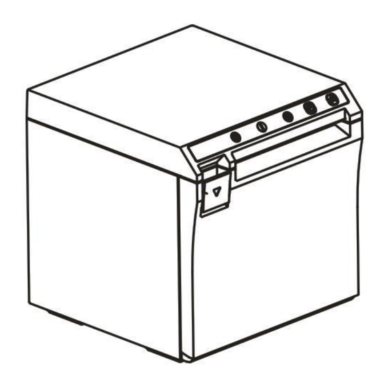
2. Appearance and Components 2.1 Appearance of the Product 1--Cutter and moving knife set 2--Rack of cartridge 3--Flip cover 4--Partition board 5--Base 6--Front cover 7--FEED Paper feed key 8--POWER Power key 9--POWER Power indicator 10--ERROR Status indicator 11--PAPER Paper lacking indicator 12--Fixed knife set 13--Rubber roller 14--Gear of rubber roller... -
Page 7: Connecting Diagram For Components Of Control Panel
2.2 Connecting Diagram for Components of the Control Panel The printer composed of main control board, printing cartridge, cutter, keys and buttons is connected to the mainboard via connectors or pinboard, and the following is the connecting diagram of USB+network interface and USB+serial interface control panel assembly:... -
Page 9: Interfaces Of The Printer
2.2 Interfaces of the Printer 2.3.1 Power interface SIGNAL NAME +24V SHELL 2.3.2 Interface of Cash drawer Cashier-box control: 6-line RJ-11 socket, output DC 24V/1A power signals to drive actions of Cash drawer. SIGNAL NAME FGND Drawer 1 CASH Drawer 2 2.3.3 USB interface SIGNAL NAME VBUS... - Page 10 2.3.4 Serial interface SIGNAL NAME 2.3.5 Network interface SIGNAL NAME GREEN+ GREEN - YELLOW+ YELLOW...
-
Page 11: Keys, Buttons, Indicators And Functions
3. Keys, Buttons, Indicators and Functions 3.1 Paper-feed key When the printer does not alarm, press the key to feed paper, and hold it to feed paper continuously. 3.2 Power key Press this key 1-2 seconds to turn on/off the printer. 3.3 Power indicator The indicator light is blue in color. -
Page 12: Installation And Use
4. Installation and Use 4.1 Connection of Interfaces 4.1.1 Connecting to power adaptor 1)Confirm that the power switch of the printer is in off state; 2)Insert the cable plug of the power adaptor into the power interface at the rear of the printer with the flat and straight facing upwards;... -
Page 13: Load Of Paper Roll
4.2 Load of Paper Roll After the power adaptor is connected to the interface cable, media can be loaded for printing, and confirm the specification of the paper used by the printer before printing. Choose the partition board as per the specification of the paper to be used. -
Page 14: Guide On Trouble-Shooting
5. Guide on Trouble-shooting In case any fault occurs for the printer, it can be handled in accordance with this chapter, If the fault cannot be solved in this way, contact the dealer or the manufacturer. 5.1 Power Supply 5.2 Printing... -
Page 15: Paper Feed
5.3 Paper Feed 5.4 Cash drawer 5.5 Indicator/Buzzer... -
Page 16: Communication
5.6 Communication 5.7 Paper Cutting... -
Page 17: Dismantlement And Assembly Of Main Parts
6. Dismantlement and Assembly of Main Parts Cautions in operation: 1) When the printer is working normally, do not dismantle any part of the printer, nor loosen any screw of the printer; 2) While dismantling parts, check if the connecting cable is damaged or not carefully; 3) In the process of handling the printing cartridge and electronic elements, taking anti-static measures;... - Page 18 6.1.2 Dismantlement of the base of the printer Picture Illustration Dismantle the two H3*6mm screws for fixing the front cover with a cross screwdriver. Move downwards for 2.5mm along the direction indicated with the arrow (Caution: do not pull out the front cover directly) Take off the front cover gently.
- Page 19 6.1.3 Dismantlement of the Flip Cover of the Printer Picture Illustration Dismantle the BM2*3mm screw for fixing the cover-opening button with a small cross screwdriver, and then take off the cover-opening button. First press the cover-opening button and open the flip cover, then move the flip cover for 12mm along the direction indicated with the arrow.
- Page 20 6.1.4 Dismantlement of the Mainboard and Pinboard of the Printer Picture Illustration Dismantle the two H3*6mm screws for fixing the mainboard with a cross screwdriver, and then take off the mainboard. Dismantle the two H3*6mm fixing the interface board with a cross driver.
-
Page 21: Cleaning Of The Printer
7. Cleaning the Printer Dust, foreign matters, sticky substance or other dirt struck on the printing head or inside the printer may lower printing quality. Clean the printer with the following method. 7.1 Clean the Printing Head 1) Open the flip cover of the printer, and clean the printer from its center to the two sides with a cleaning pen or a cotton stick moistened with diluted alcohol (alcohol or isopropanol). -
Page 22: Appendix: Exploded View Of The Printer
Appendix: Exploded View of the Printer 1. List of Parts of the Printer Name of material Name of material Partition board Label for keys Paper compartment Front cover Left supporting board Blade Stationary knife Thermal slice Lamp panel Cover-closing board Mainboard Bottom board Interface board... -
Page 23: Exploded View Of The Whole Unit Of The Printer
2. Explode View of the Printer... -
Page 24: Exploded View Of The Cartridge Of The Printer
3. Explode View of Cartridge of the Printer... - Page 25 Manufacturer: EC LINE Thank you very much for using EC Line product For service, please contact service@ecline.com.hk www.eclinepos.com...
Need help?
Do you have a question about the EC-PM-X30 and is the answer not in the manual?
Questions and answers