Table of Contents
Advertisement
Quick Links
Advertisement
Table of Contents

Related Manuals for EC Line EC-PM-80320


Summary of Contents for EC Line EC-PM-80320
- Page 1 Service Manual EC-PM-80320 Thermal Printer...
- Page 2 EC-PM-80320 Service Manual Warnings, Cautions, and Notes Pay attention to the following promises when using this manual: Warning: Warnings must be followed carefully to avoid bodily injury. Caution: Cautions must be observed to avoid damage to your equipment. Note: Notes contain important information and useful tips on the operation of your printer.
- Page 3 EC-PM-80320 Service Manual This Manual is to help qualified service engineers repair or adjust your EC-PM-80320. Please read the manual carefully before repairing and adjusting your EC-PM-80320. The warranty will not cover any trouble with or damage to the printer resulting from repair or modification by unqualified persons.
-
Page 4: Table Of Contents
EC-PM-80320 Service Manual Table of Contents Chapter 1 Printer Introduction ......................1 1.1 Explanation and application ......................1 1.2 Product type............................1 1.3 Characteristic..........................1 1.4 Parts Identification ..........................2 Chapter 2 Control Panel Operation.......................1 2.1 Control Panel ..........................1 2.1.1 Indicator LED..........................1 2.1.2 KEY ............................1 2.2 Self-Testing .............................1... - Page 5 6.4 Motor Abnormality .........................23 6.5 Cutter Abnormality ........................23 6.6 Cash Drawer Interface Abnormality ....................23 6.7 Cutter Jammed or Error ........................23 Appendix A EC-PM-80320 Exploded View ..................25 A.1 Drawing for EC-PM-80320 ......................25 A.2 Parts List for EC-PM-80320......................26 Appendix B Mechanism Exploded View.....................28 B.1 Drawing for MPM-80T ........................28...
-
Page 6: Explanation And Application
EC-PM-80320 printer is a kind of high-speed mini thermal printer with high quality, high reliability and low noise. It does not need ribbon cartridge and can be operated easily. EC-PM-80320 printer can be widely used in ECR, PC-POS and BANK POS for printing various kinds of receipts. -
Page 7: Parts Identification
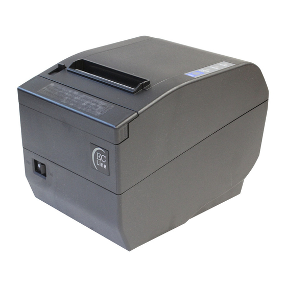
EC-PM-80320 Service Manual 1.4 Parts Identification Upper Cover Power Indicator Cover-open Button Error Indicator Manual Cutter Paper out Indicator Power Switch FEED Key Front Cover Figure 1-1 Main parts of the printer Data Interface Power Supply Inlet Cash Drawer Interface Figure 1-2 Back interfaces of the printer Note: Please take the specific interface as standard. -
Page 8: Chapter 2 Control Panel Operation
EC-PM-80320 Service Manual Chapter 2 Control Panel Operation 2.1 Control Panel There are three LEDs and one key on the control panel shown as Figure 2-1. Figure 2-1 Control panel 2.1.1 Indicator LED Indicator LED Description Denotes whether the printer’s power supply is connected or not. The indicator POWER (Green) LED is on when the power is connected. -
Page 9: Restoring Factory Printer Settings
EC-PM-80320 Service Manual terminal device works properly or not. The method is that holding down FEED key while turning on the printer, the ERROR LED blinks once with two beeps. Go on holding the key for about one second, and then loosen it after the ERROR LED blinks once again with a beep. -
Page 10: Chapter 1 Printer Introduction
EC-PM-80320 Service Manual Chapter 3 Specification 3.1 General Specification Item Description Printing method Direct thermal printing Dot density 576 dots/line (203×203 DPI) Effective printing width 72 mm Max paper feed speed 220 mm/s TF50KS-E (Japan paper co.ltd) Thermal roll paper model AF50KS-E (JUJO THERMAL) Width: 79.5 ±... -
Page 11: Interface Specification
EC-PM-80320 Service Manual Output voltage: 24 V(DC) Current: 2.5 A Temperature: 5 ~ 35℃ Operating environment Humidity: 25 ~ 80%RH (No condensation) Environmental conditions Temperature: -40 ~ 55℃ Storage environment Humidity: ≤93%RH (40℃, No condensation) Weight Approx. 2 Kg Noise <38 dB (A) (ISO7779 standard) -
Page 12: Parallel Interface
Table 3-1 Cash drawer connector Pin assignments Note: Please use the cash drawer that meets the specification mentioned above. Manufacturer will not honor warranty when using unauthorized cash drawer. 3.2.2 Parallel Interface EC-PM-80320 printer’s parallel interface is compatible with protocol, supporting CENIRONICS BUSY/ACK handshaking protocol. -
Page 13: Usb Interface
Black Figure 3-4 USB interface 3.2.4 Serial Interface EC-PM-80320 printer’s serial interface is compatible with RS-232C protocol, supporting RTS/CTS and XON/XOFF handshaking protocol. Its connector is a DB-9 type connector and each pin’s definitions are shown as figure 3-5. Figure 3-5 Sequence numbers of Serial connector... -
Page 14: Ethernet Interface
3.2.5 Ethernet Interface Ethernet interface of 10/100 Base-T can be connected to 10/100M. Figure 3-8 Ethernet interface 3.2.6 Power Supply Inlet The EC-PM-80320 printer connects with a 24V±10% and 2.5A AC adapter. The power supply inlet is - 5 -... - Page 15 EC-PM-80320 Service Manual shown as Figure 3-9. Figure 3-9 Power supply inlet - 6 -...
-
Page 16: Chapter 4 Printer Working Principle
4.1 Working Principle of Thermal Print Head EC-PM-80320 has one thermal print head which is made up of 640 fever dot-size components. The print result is formed through thermal print head dot-matrix heating the thermal paper which is to be black and matching the paper feed. -
Page 17: The Structure Of Thermal Head
LATCH signal cycle time. Later on, print start-up signal (DST1, 2) will heat the corresponding fever component according to the data latched in the latch-register. EC-PM-80320 thermal head prints 128 dots per section according to the print content. -
Page 18: Print Position Of Data
EC-PM-80320 Service Manual 4.1.3 Print position of data The 384 dots from 1 to 384 are transmitted through DATA IN1, and the 256 dots from385 to 640 are transmitted through DATA IN2.The print position of all data dots are shown as follows:... -
Page 19: Timing Signal Figure
Figure 4-5 Timing Signal Figure 4.1.6 Thermal Head Resistance The resistance of EC-PM-80320 thermal head is about 630.5 to 669.5Ω. 4.1.7 Thermal Head Voltage There is a drive IC inside the printer, whose drive voltage is from 21.6 to 26.4V and logical voltage is from 4.75 to 5.25V. -
Page 20: Thermal Sensor
4.2.1.1 Checking the excrescent temperature of print head EC-PM-80320 printer checks the excrescent temperature through soft and hardware. The print head will stop heating the fever component when the temperature is higher than 80℃ (thermal resistance is lower than 3.80 KΩ). -
Page 21: Paper Sensor
Table4-3 Corresponding value of thermal resistance 4.2.2 Paper Sensor EC-PM-80320 printer has two sensors (the light glint type) inside which are used to check whether there is paper, and also establishes an external electric circuit to check the output of sensor. One sensor is set under the print head, and the printer will stop printing when lack of paper is detected by this sensor, and it is valid by default. -
Page 22: Platen Position Sensor
The maximum rating of the sensor: 7VDC, 1mA; relative resistance: 70mΩ at most. 4.3 Working Principle of Control Unit 4.3.1 Structure module Figure 4-7 is the main structure module of EC-PM-80320. Control Panel Host computer Parallel interface... -
Page 23: Part's Main Function
8. Standard interface The EC-PM-80320 printer is configured with a cash drawer interface and a data interface (parallel interface, USB interface, USB interface + serial interface, USB interface + Ethernet interface, USB interface + Bluetooth, USB interface + Wi-Fi). - Page 24 EC-PM-80320 Service Manual CN5: Connect to cutter of printer mechanism. (Shown as table 4-8) CN10: Connect to paper end sensor. (Shown as table 4-9) CN12: Control panel connected socket. (Shown as table 4-10) 1~4 Drive signal thread of paper-feed motor...
-
Page 25: Control System's Principle Frame
EC-PM-80320 Service Manual 4.3.4 Control System’s Principle Frame Thermal motor control system’s principle frame: Power indicator Error indicator (FEED) key Paper out indicator Electrify replacement 8MB SDRAM SPI Flash Address Top case sensor 16-bit Paper sensor Data Bus Paper near end sensor... -
Page 26: Chapter 5 Printer Installation And Removing
EC-PM-80320 Service Manual Chapter 5 Printer Installation and Removing Warning: 1. Before installing/removing or adjusting the printer, you should unplug the power cord from the electrical outlet. 2. Be careful of the cutter because of its sharpness. 3. Thermal head is a sensitive part, therefore, please don’t touch the thermal head with your hand or other hard thing at any time. -
Page 27: Removing The
EC-PM-80320 Service Manual 5.1.2 Removing the front cover Pull the front cover frontward until it meets resistance and then pull it upwards. Front cover Figure 5-2 5.1.3 Removing the Upper Housing Step1. Close the upper cover. Step2. As Figure 5-3 shown, loosen the screws PWM3*5*7;... -
Page 28: Disassemble Mpm-80T Printer Assembly
EC-PM-80320 Service Manual Step4. Loosen four screws. Step5. As Figure 5-5 shown, press the power switch to be symmetric, pull out the bottom housing, while which still blocks the switch, you can gently turn over the border of bottom housing outward. -
Page 29: Disassemble Mpm-80T Assembly
EC-PM-80320 Service Manual Baseplate cover Screw PM3*4 Figure 5-8 Figure 5-7 5.2.2 Disassemble MPM-80T Assembly Step1. As Figure 5-9 shown, loosen the screws PM3*6. Step2. Take down the MPM-80T assembly. Screw PM3*6 MPM-80T assembly Figure 5-9 Note:MPM-80T assembly doesn’t need maintenance, and it doesn’t need any lubrication under the normal condition. -
Page 30: Loosen Rolling Ring
EC-PM-80320 Service Manual Screw PM3*4 Figure 5-10 5.3.2 Loosen Rolling Ring Step1. Pull out the feed paper gear. Step2. Take off the E-ring Ф1.5, Then the rolling ring on both sides can be slid out. Rolling ring 2 Feed paper gear C Rolling ring E-ring Ф1.5... -
Page 31: Installation Of Printer
EC-PM-80320 Service Manual Figure 5-13 5.4 Installation of Printer Installation of printer follows the reverse procedure of disassembly. When installing the printer, you must tighten the screws, and confirm that all the cables are connected correctly. Don’t install incorrectly or miss some parts. If not need, please don’t connect the power before installation is finished. -
Page 32: Chapter 6 Troubleshooting
EC-PM-80320 Service Manual Chapter 6 Troubleshooting 6.1 Error Message on the Control Panel When the malfunction is occurred, the printer will be off-line and give an alarm through LEDs. You can make out different malfunctions through the Table 6-1 shown below. - Page 33 EC-PM-80320 Service Manual return to the normal position after the printer is restarted, please pull out the front cover which locates above the auto-cutter to expose the auto-cutter. Then turn the gear in the arrow direction. If the gear can’t be moved in the arrow direction, don’t force it, please turn it in the reverse direction until the auto-cutter returns to the normal position.
-
Page 34: Appendix A Ec-Pm-80320 Exploded View
EC-PM-80320 Service Manual Appendix A EC-PM-80320 Exploded View A.1 Drawing for EC-PM-80320 (See Figure A-1) Figure A-1 - 25 -... -
Page 35: Parts List For Ec-Pm-80320
EC-PM-80320 Service Manual A.2 Parts List for EC-PM-80320 Parts name Note Screw PM3X6 100000000770 Mechanism assembly 200000000508 Label 2 510000010892 Printer connected flat cable 100000001782 Mechanism frame 100000001009 Screw PM3X4 100000000929 Mechanism support 100000001008 Screw M3X5X7 100000000966 Top cover (black) - Page 36 EC-PM-80320 Service Manual USB interface assembly 200000028392 USB + Serial interface assembly 200000028150 Parallel interface assembly 200000028171 Screw PM2.5X3 100000000954 Platen frame 100000001010 Paper end sensor assembly 200000000428 Paper holder house 100000001012 Control panel assembly 200000000381 Slide shaft 100000001014 Paper holder...
-
Page 37: Appendix B Mechanism Exploded View
EC-PM-80320 Service Manual Appendix B Mechanism Exploded View B.1 Drawing for MPM-80T Figure A-2 - 28 -... -
Page 38: Parts List For Mpm-80T Drawing
EC-PM-80320 Service Manual B.2 Parts List for MPM-80T Drawing Parts name Note Paper feed motor 100000051980 Screw BM2X2 100000001038 Knob support plate 100000001021 Screw PM3x4 100000000929 Paper feed gear A 200000025707 E-ring Φ1.5 100000000940 Paper feed gear B 200000025706 E-ring Φ2.0... - Page 39 EC-PM-80320 Service Manual Sensor spacer 100000001037 Screw PA2.5x8 100000000926 Photoelectric sensor 100000000950 Screw DB1.4x8 100000001040 - 30 -...
-
Page 40: Appendix C Main Control Pcb Circuit Diagram
EC-PM-80320 Service Manual Appendix C Main control PCB circuit diagram - 31 -... - Page 41 EC-PM-80320 Service Manual - 32 -...
- Page 42 EC-PM-80320 Service Manual - 33 -...
- Page 43 EC-PM-80320 Service Manual - 34 -...
- Page 44 EC-PM-80320 Service Manual - 35 -...
Need help?
Do you have a question about the EC-PM-80320 and is the answer not in the manual?
Questions and answers