Table of Contents
Advertisement
Available languages
Available languages
Quick Links
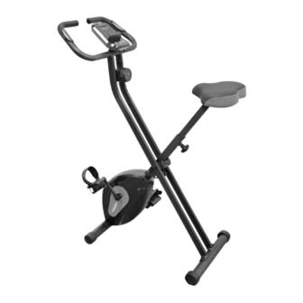
X-BIKE
KLAPPHEIMTRAINER
Montage- und Bedienungsanleitung
Bestell-Nr.: 2401
DE
Seite: 2-11
Assembly and operating instructions
Order No.: 2401
GB
Page: 12-20
Instructions de montage et d'utilisation
F
No. de commande: 2401
Page: 21-29
Montage- en bedieningsinstructies
Bestellnr.: 2401
NL
Pagina: 30-38
Návod k montáži a použití pro
Objednací číslo: 2401
CZ
Strana: 39-47
1
Advertisement
Table of Contents

Related Manuals for Christopeit Sport X-BIKE


Summary of Contents for Christopeit Sport X-BIKE
- Page 1 X-BIKE KLAPPHEIMTRAINER Montage- und Bedienungsanleitung Bestell-Nr.: 2401 Seite: 2-11 Assembly and operating instructions Order No.: 2401 Page: 12-20 Instructions de montage et d'utilisation No. de commande: 2401 Page: 21-29 Montage- en bedieningsinstructies Bestellnr.: 2401 Pagina: 30-38 Návod k montáži a použití pro Objednací...
-
Page 2: Table Of Contents
INHALTSÜBERSICHT Seite Inhalt Christopeit-Sport Community Garantiebestimmungen Wichtige Empfehlungen und Sicherheitshinweise Montageanleitung Benutzung des Gerätes Computerbeschreibung Reinigung, Wartung und Lagerung Störungsbeseitigung Trainingsanleitung Allgemein 10-11 Stückliste - Ersatzteilliste Explosionszeichnung SEHR GEEHRTE KUNDIN, SEHR GEEHRTER KUNDE, wir gratulieren Dir zum Kauf dieses Heimsport-Trainingsgerätes und wünschen Dir viel Vergnügen damit. Bitte beachte und befolge die Hinweise und Anweisungen dieser Montage- und Bedienungsanleitung. -
Page 3: Wichtige Empfehlungen Und Sicherheitshinweise
WICHTIGE EMPFEHLUNGEN UND SICHERHEITSHINWEISE Unsere Produkte sind grundsätzlich TÜV geprüft und entsprechen Achtung! Vor Benutzung damit dem aktuellen, höchsten Sicherheitsstandard. Diese Tatsache Bedienungs- entbindet aber nicht die nachfolgenden Grundsätze strikt zu anleitung lesen! befolgen. Das Gerät genau nach der Montageanleitung aufbauen und nur Achtung! Wenn Schwindelgefühle, Übelkeit, Brustschmerzen die, für den Aufbau des Gerätes beigefügten und in der Montage oder andere abnormale Symptome wahrgenommen werden, das... -
Page 4: Montageanleitung
MONTAGEANLEITUNG Entnehmen Sie alle Einzelteile der Verpackung, legen diese auf den Boden und kontrollieren die Vollzähligkeit grob anhand der Montageschritte. Montagezeit ca. 15-20 Min. SCHRITT 1 Montage der Fußrohre (24+47) an den beiden Grundrahmen (6+27). 1. Ziehen Sie den Sicherheitsstift (28) heraus, um die beiden Grundrahmen (6+27) auseinander zu klappen. - Page 5 SCHRITT 3 Montage der Pedalen (18+53) an den Pedalarmen (20+51). 1. Die Pedalen und Pedalsicherungsbänder sind mit „R“ für Rechts und „L“ für Links gekennzeichnet. 2. Die rechte Pedale (53) in das Gewindeloch des rechten Pedalarmes (51) eindrehen und fest anziehen. (Achtung! Rechts und Links sind aus der Blickrichtung zu sehen, wenn man auf dem Gerät sitzt und trainiert.
-
Page 6: Benutzung Des Gerätes
BENUTZUNG DES GERÄTES Funktion des Klappmechanismusses Aufsteigen Einstellen der Trainingsposition Halten Sie sich am Lenker fest. Führen Sie die naheliegende Pedale zur untersten Position und schieben Sie den Fuß unter 1. Um das Gerät platzsparend aufzubewahren, entfernen das Pedalsicherungsband ein, sodass Sie einen sicheren Stand Sie den Sicherungsstift (28) aus dem Antriebsrahmen (27). -
Page 7: Computerbeschreibung
COMPUTERBESCHREIBUNG Der mitgelieferte Computer bietet den größten Trainingskomfort Jeder trainingsrelevante Wert wird in einem entsprechenden Sichtfenster angezeigt. Vom Trainingsbeginn an werden die benötigte Zeit, die aktuelle Geschwindigkeit, der ungefähre Kalorienverbrauch, zurückgelegte Entfernung und der aktuelle Puls angezeigt. Alle Werte werden von Null an aufwärts zählend festgehalten. Wollen Sie permanent einen Wert während des Trainings angezeigt haben, so wählen Sie diesen mit der [M] Taste aus. -
Page 8: Reinigung, Wartung Und Lagerung
PULSMESSUNG AUSTAUSCH DER BATTERIEN 1. Handpulsmessung Öffnen Sie den Batteriefachdeckel und entnehmen linken rechten Lenkergriffteil eine Sie die gebrauchten Batterien. (Sollten die Batterien Metallkontaktplatte, die Sensoren, eingelassen. Bitte darauf ausgelaufen sein entfernen Sie diese unter erhöhter achten, dass immer beide Handflächen gleichzeitig mit Berücksichtigung, dass die Batteriesäure nicht mit Haut normaler Kraft auf den Sensoren aufliegen. -
Page 9: Trainingsanleitung Allgemein
TRAININGSANLEITUNG ALLGEMEIN Um spürbare, körperliche und gesundheitliche Verbesserungen zu 02: Trainingspuls-Berechnen erreichen, müssen für Bestimmung erforderlichen Durch meine Ziele Trainingsgrad passt für mich Trainingsaufwandes folgende Faktoren beachtet werden. Fettstoffwechsel-Zone am besten. Trainingspuls = 60 bis 70% von dem Maximalpuls INTENSITÄT Trainingspuls = 190 x 0,6 [60%] Die Stufe der körperlichen Belastung beim Training muß... -
Page 10: Stückliste - Ersatzteilliste
STÜCKLISTE - ERSATZTEILLISTE Artikel: X-Bike Art.-Nr.: 2401 15.04.2024 Stand der technische Daten: Stellmaß [cm]: L 81 x B 46 x H 117 cm Stellmaß geklappt [cm]: L 49 x B 46 x H 136 cm Trainingsplatzbedarf [m Gerätegewicht [kg]: 14,5 kg Benutzergewicht von max. - Page 11 Abmessung Montiert an Abb.- Nr. Bezeichnung Menge ET Nummer Abb. Nr. Achsmutter schmal 39-9820 Sensorkabel 5+43 36-2402-13-BT Sensorhalter 36-9808-10-BT Kreuzschlitzschraube M6x10 27+36 39-9911 Spannrolle 33-2402-17-SI Endkappe mit Transportrolle 36-1205-25-BT Fußrohr vorne 33-2402-04-SW Kreuzschlitzschraube 3x10 46+47 39-10127-SW Verkleidung rechts 21+27 36-2401-02-BT Kreuzschlitzschraube 4x30 21+50...
- Page 12 CONTENTS DEAR CUSTOMER, Page Contents We congratulate you on your purchase of this home training sports unit and hope that we will have a great deal of pleasure Important recommendations and safety instructions with it. Please take heed of the enclosed notes and instructions 13-14 Assembly instructions and follow them closely concerning assembly and use.
- Page 13 ASSEMBLY INSTRUCTIONS Remove all the separate parts from the packaging, lay them on the floor and check roughly that all are there on the base of the assembly steps. Assembly time approx. 15-20 minutes. STEP 1 Install of front and rear foot (24+47) to the main frames (6+27).
- Page 14 STEP 3 Installation of right and left pedal (18+53) at pedal cranks (20+51). 1. The pedals and pedals straps are marked “R” for right and “L” for left. 2. Screw the right pedal (53) into the threaded hole on the right hand side of the pedal crank (51) and tighten firmly.
- Page 15 USE OF THE DEVICE Function of the folding mechanism Mount Adjusting the training position Hold on to the handlebar. Insert your foot into retaining strap of pedal step on the pedal. Try to put whole body weight on your 1. To save space when storing the device, remove the safety foot and simultaneously cross over the trainer and land your pin (28) from the drive frame (27).
- Page 16 COMPUTER COMPUTER INSTRUCTIONS The supplied computer allows the most convenient training. Every value relevant to training is displayed in a corresponding window. From the beginning of the training session, the required time, the current speed, the approximate calorie consumption, the travelled distance ad the current pulse rate are displayed.
- Page 17 PULSE RATE REPLACING THE BATTERIES Open the battery compartment cover and then remove 1. Hand pulse measurement the used batteries.(If the batteries should leak remove On the left and right side of handlebar two metal contact plates them under increased considering that the battery acid are insert as pulse sensors.
- Page 18 GENERAL TRAINING INSTRUCTIONS You must consider the following factors in determining the amount of 02: Training heart rate calculation training effort required in order to attain tangible physical and health Due to my goals and training level, the fat metabolism zone benefits.
- Page 19 PARTS LIST – SPARE PARTS LIST Type: X-Bike Order-Nr.: 2401 15.04.2024 Date of technical data: Dimensions approx: [cm]: L 81 x B 46 x H 117 cm Folded approx: [cm]: L 49 x B 46 x H 136 cm Space requirements [m Weight approx.
- Page 20 Illustration Designation Dimension mm Quantity Attached to ET Number Axle nut thin 39-9820 Sensor cable 5+43 36-2402-13-BT Sensor holder 36-9808-10-BT Cross head screw M6x10 27+36 39-9911 Idle wheel 33-2402-17-SI End cap with transportation roller 36-1205-25-BT Front stabilizer 33-2402-04-SW Cross head screw 3x10 46+47 39-10127-SW...
- Page 21 SOMMAIRE CHÈRE CLIENTE, CHER CLIENT, Page Contenu Nous vous félicitons pour l’achat de ce cycle d’entraînement intérieur et nous vous souhaitons beaucoup de plaisir avec. Recommandations importantes et consignes Veuillez respecter et suivre les indications et les instructions de de sécurité montage et d’emploi.
- Page 22 INSTRUCTIONS DE MONTAGE Sortez toutes les pièces de l’emballage, posez-les sur le sol et contrôlez si rien ne manque en vous basant grossièrement sur la étapes de montage. Temps de Montage : 15-20 min. ETAPE 1 Montage du tube du pied avant et arrière (24+47) sur le cadre de base (6+27).
- Page 23 ETAPE 3 Montage de la pédale droite et gauche (18+53) sur les pédaliers (20+51). 1. Les pédales (18+53) et les bandes cale-pied (74+75) est marquée avec un „R“ et un „L“. 2. Visser la pédale droite (53) dans le trou taraudé situé sur la partie latérale droite de pédalier droit (51) et serrer à...
- Page 24 MONTER, UTILISER & DESCENDRE Fonction du mécanisme de pliage / Monter réglage de la position d’entraînement: Accrochez-vous au guidon. Insérez votre pied dans la sangle de retenue du pédalier sur la pédale. Essayez de mettre votre 1. Pour ranger l’appareil dans un espace réduit, retirez poids entier sur ce pied et en même temps, levez l’autre jambe la goupille de sécurité...
- Page 25 COMPUTER COMPUTER INSTRUCTIONS L’ordinateur livré vous offre le plus grand confort d‘entraînement. Chaque valeur importante pour l’entraînement est affichée dans une fenêtre. Le temps nécessaire, la vitesse actuelle, la consommation de calories approximative, la distance parcourue et le pouls actuel sont affichés dès le commencement de l’entraînement.
- Page 26 RYTHME CARDIAQUE REMPLACEMENT DES PILES: 1. Mesure du pouls sur la main Ouvrez le couvercle du compartiment de la pile, puis Le guidon a droite et gauche comportent chacune un capteur retirez le utilisée piles. (Si les piles fuient les supprimer (pièces de contact métalliques.) Attention, veillez à...
- Page 27 CONSIGNES GÉNÉRALES DE FORMATION Les facteurs ci-après doivent être pris en compte pour la détermination de 01 : Impulsion maximale - calcul l’entraînement indispensable afin d’améliorer concrètement son physique et Fréquence cardiaque maximale = 214 - (0,5 x âge) - (0,11 x poids) sa santé.
- Page 28 LISTE DES PIÈCES- LISTE DES PIÈCES DE RECHANGE Désignation: X-Bike No. de commande: 2401 15.04.2024 Caractéristiques version du: Dimension environ [cm]: L 81 x B 46 x H 117 cm Dimension plié [cm]: L 49 x B 46 x H 136 cm...
- Page 29 Schéma Dimensions Quantité Monté sur Désignation Numéro ET N° en mm Unités schéma n° Ecrou d’axe 39-9820 Câble de capteur 5+43 36-2402-13-BT Support de capteur 36-9808-10-BT Vis cruciforme M6x10 27+36 39-9911 Rouleau tendeur 33-2402-17-SI Chapeaux finaux avec roulette de transport 36-1205-25-BT Tube de Piet avant 33-2402-04-SW...
- Page 30 INHOUDSOPGAVE GEACHTE KLANT Pagina Inhoud Wij willen u van harte gelukwensen met de aanschaf van uw hometrainer en hopen dat u hier veel plezier aan zult beleven. Belangrijke aanbevelingen en veiligheidsinstructies Neem a.u.b. de instructies en aanwijzingen uit deze montage- en 31-32 Montagehandleiding bedieningshandleiding in acht en volg deze op.
- Page 31 MONTAGEHANDLEIDING Neem alle losse onderdelen uit de verpakking, leg deze op de grond en bruto controleer aan de hand van de montageen staps of alle onderdelen aanwezig zijn. Montage tijd: 15-20 min. STAP 1 Montage van de voorste en achterste voetbuis (24+47) op het framen (6+27).
- Page 32 STAP 3 Montage van de rechter en linker trapper (18+53) op de pedaalkruk (20+51). 1. De trappers en pedalvastzetbanden worden met „R“ voor rechts en „L“ voor links aangeduid. 2. De rechter trapper (53) in het schroefdraadgat op de rechterzijde van de pedaalkruk (51) draaien en stevig vastdraaien.
- Page 33 OPSTAPPEN, GEBRUIKEN & AFSTAPPEN Functie van het klapmechanisme / Opstappen verstellen van de trainingspositie: Houd het stuur vast. Steek uw voet in de bevestigingsband van de pedaaltrap op het pedaal. Probeer uw gewicht nu op deze voet te brengen en tegelijkertijd uw andere been over het 1.
- Page 34 COMPUTERHANLEIDING bijgeleverde computer zorgt voor uitstekend trainingscomfort. Elke trainingsrelevante waarde wordt in het venster weergegeven. Vanaf het begin van de training worden de benodigde tijd, de actuele snelheid, het verbruikte aantal calorieën, de afgelegde afstand en de actuele hartslag weergegeven. Vanaf nul worden alle waarden verhoogd en vastgehouden.
- Page 35 HARTSLAG VERVANGEN VAN DE BATTERIJEN Open het deksel van het batterijcompartiment en 1. Handpulsmeting verwijder de gebruikte Batterijen. (Als de batterijen In het linkse en rechtse stuurgedeelte is telkens een metalen lekken verwijder ze onder toegenomen gezienhet feit dat contactplaat, de voelers, voorzien. Gelieve erop te letten dat het accuzuur niet in aanraking met de huid komen en steeds beide handpalmen gelijktijdig met normale kracht op reinig het batterijcompartiment grondig.)
- Page 36 ALGEMENE TRAININGSINSTRUCTIES U moet rekening houden met de volgende factoren bij het bepalen van 02: Training hartslagberekening Door mijn doelen en trainingsniveau past de vetstofwisselingszone het bedrag van trainingsinspanning die nodig is om tastbare fysieke en gezondheid te bereiken voordelen. het beste bij mij.
- Page 37 STUKLIJST – LIJST MET RESERVEONDERDELEN Aanduiding: X-Bike Bestellnr.: 2401 15.04.2024 Stand technische gegevens: Afmetingen ca: [cm]: L 81 x B 46 x H 117 cm Afmetingen opgevouwen ca: [cm]: L 49 x B 46 x H 136 cm Ruimtevereisten [m Productgewicht ca.
- Page 38 Afbeeldings Afmetingen Aantal Gemonteerd aan Beschrijving ET-nummer stuks afbeeldings nr. Riemtransmissie 39-9820 Asmoer smal 5+43 36-2402-13-BT Sensor 36-9808-10-BT Sensor houder M6x10 27+36 39-9911 Kruiskopschroef 33-2402-17-SI Spanrol met houder 36-1205-25-BT Voetkappen met tranportrollen 33-2402-04-SW Voorste voetbuis 3x10 46+47 39-10127-SW Kruiskopschroef 21+27 36-2401-02-BT Bekleding Rechts 4x30...
- Page 39 OBSAH VÁŽENÁ ZÁKAZNICE, Strana Obsah Důležitá doporučení a bezpečnostní pokyny 40-41 Blahopřejeme vám k vašemu nákupu této domácí tréninkové Montážní návod sportovní jednotky a doufáme, že si s ní užijete spoustu Používání přístroje 43-44 potěšení. Věnujte prosím pozornost přiloženým poznámkám Pokyny k počítači a pokynům a pečlivě...
- Page 40 MONTÁŽNÍ NÁVOD Vyjměte všechny jednotlivé díly z obalu, položte je na podlahu a pomocí montážních kroků zhruba zkontrolujte, zda jsou kompletní. Doba montáže cca 15-20 minut. KROK 1 Montáž nožních trubek (24+47) na dva základní rámy (6+27). 1. Vytáhněte pojistný kolík (28) a složte dva základní rámy (6+27) od sebe.
- Page 41 KROK 3 Montáž pedálů (18+53) na ramena pedálů (20+51). 1. Pedály a zajišťovací popruhy pedálů jsou označeny „R“ vpravo a „L“ pro levou stranu. 2. Našroubujte pravý pedál (53) do závitového otvoru pravého ramena pedálu (51) a pevně jej utáhněte. (Pozor! Pravá...
- Page 42 POUŽÍVÁNÍ PŘÍSTROJE Funkce skládacího mechanismu / Nastupování nastavení tréninkové polohy: Držte se řídítek. Vložte nohu do přídržného popruhu pedálu na pedálu. Nyní přeložte druhou nohu k pedálu na protilehlé straně 1. Chcete-li zařízení uložit, abyste ušetřili místo, vytáhněte a přitom se posaďte na sedlo. Přitom se rukama pevně držte pojistný...
- Page 43 POKYNY K POČÍTAČI Počítač, který je součástí tohoto balení, nabízí nejvyšší možný tréninkový komfort. Všechny hodnoty, které jsou pro trénink relevantí, se zobrazí v odpovídajícím políčku na ukazateli. Jakmile zahájíte trénink, začne se zobrazovat uplynulý čas, aktuální rychlost, přibližná spotřeba kalorií, ujetá vzdálenost a aktuální...
- Page 44 TEPOVÁ FREKVENCE VÝMĚNA BATERIÍ Otevřete kryt zdířky baterie vyjměte 1. Měření tepu ruky vybité baterie. (Pokud baterie vytekla, Na levé a pravé části rukojeti řídítek jsou vloženy dvě kovové odstraňte zvýšenou opatrností tak, kontaktní destičky jako snímače tepu. Dbejte prosím na to, aby kyselina baterií...
- Page 45 Všeobecné pokyny pro školení Abyste dosáhli znatelného tělesného a zdravotního zlepšení, musíte při 02: Výpočet tréninkové tepové frekvence určování potřebného tréninku dbát následujících faktorů. Vzhledem k mým cílům a tréninkové úrovni mi nejvíce vyhovuje zóna metabolismu tuků. INTENZITA Tréninková tepová frekvence = 60 až 70 % maximální tepové Úroveň...
- Page 46 SEZNAM DÍLŮ – SEZNAM NÁHRADNÍCH DÍLŮ Označení: X-Bike Objednací číslo: 2401 15.04.2024 Datum technických údajů: Rozměry cca: [cm]: D 81 x Š 46 x Š 117 cm Rozměry ve složeném stavu cca.[cm]: L 49 x Š 46 x Š 136 cm Prostorové...
- Page 47 Obr. č. Popis Rozměry Množství namontované na ET čísle Matice nápravy úzká 39-9820 Kabel snímače 5+43 36-2402-13-BT Držák senzoru 36-9808-10-BT Phillips šroub M6x10 27+36 39-9911 Napínací válec 33-2402-17-SI Koncovka s transportním válečkem 36-1205-25-BT Přední nožní trubka 33-2402-04-SW Phillips šroub 3x10 46+47 39-10127-SW Kapota vpravo...
- Page 48 NOTIZEN / NOTES / REMARQUES / ANMERKUNGEN / POZNÁMKY...
- Page 52 Service / Hersteller Bei Reklamationen, notwendigen Ersatzteilbestellungen oder Reparaturen wenden Sie sich bitte an unsere Service Abteilung. Top-Sports Gilles GmbH Friedrichstrasse 55 Tel.: +49 (0)2051/6067-0 Fax: +49 (0)2051/6067-44 D - 42551 Velbert info@christopeit-sport.com http://www.christopeit-sport.com © by Top-Sports Gilles GmbH D-42551 Velbert (Germany)
Need help?
Do you have a question about the X-BIKE and is the answer not in the manual?
Questions and answers