Advertisement
Quick Links
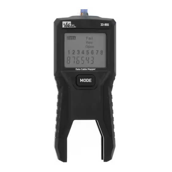
Data/Ethernet LCD Wiremapper
Instruction Manual
Introduction
The 33-855 LCD Wiremapper provides a simple way to map out 8 conductor twisted pair connec-
tions, verify wiring pinouts, and display detailed faults on RJ45 terminated cables. Installed cabling
terminated with RJ45 jacks can also be tested when using patch cables (not supplied) to connect to
the main unit and remote to the jacks. A built-in tone generator can be used for tracing and locating
cables in wiring closets and patch panels. An analog amplifier probe (sold separately) is required to
make the tone signal audible.
Safety Information
Risk of personal injury or risk of damage or destruction to equipment. Risk of electric shock. See
manual for details. Read manual before using.
WARNING
This manual includes attention and safety rules that must be followed for the safety of the user and
the instrument. Please read and understand the instructions before use.
• Do not place or use the instrument in dusty, high temperature, humid or wet environments.
• The main unit is powered by 2 x 1.5 AAA batteries. Do not use other batteries to power the
instrument.
• Remove the battery when the instrument will not be used for a longer period of time.
• Do not use this instrument on known live circuits. Test circuits for voltage before connecting.
• Do not connect the tester to a live circuit. Exposure to voltage can damage the tester
• Visually inspect an RJ45 plug before inserting it into the tester. Poorly terminated plugs may
damage the jacks on the tester.
• Do not plug a 6 position connector (RJ11/RJ12) into the tester. Damage to the test jacks may
occur.
• Replace the batteries immediately when the low battery warning appears. Test results may not be
accurate when the low battery warning is on.
Package Contents
• (1) Main Test Unit
• (2) 1.5V AAA Batteries
• (1) Remote Unit
• (1) Instruction Manual
Features
Tester Description
1) LCD Display
2) Mode Button
3) Detachable Remote
LCD Display
RJ45 Jack
Row 1
Data: Appears when testing or
toning a network cable.
Pass: Indicates proper wiring on cable being tested.
Fail: Indicates wiring error on cable being tested.
Tone: Appears when the tone generator is activated.
Row 2
Volt!: Flashes when the tester is connected to a cable with
voltage on it. Exposure to voltage can damage the tester. If this
warning appears, immediately disconnect the cable from the tester.
X-over: Appears when the tester detects a properly wired
cross over cable.
Rev: Appears when the cable has reversed and crossed
connections.
Short: Indicates that two or more wires are shorted to each other.
Row 3
Low battery Icon: When this symbol appears, the battery should be replaced immediately.
Shield: Appears when the cable being tested has a shield that is connected at both ends. The
Shield indicator will flash if there is a short between the shield and any wire within the cable.
Open: Appears when one or more pairs are open.
Split: Appears when the tester detects the signal is split between two or more pairs.
Row 4
Wire Map near end: Top row of numbers displays the connector pins on the tester end of the
cable in numerical order. These will always show 1-8 and not change.
Row 5
Wire Map remote end: Bottom row of numbers displays the corresponding pin numbers on
the remote end of the cable. These numbers will change. Dash lines indicate shorted pins. No pin
numbers indicate an open pair.
Using the LCD Wiremapper
WARNING: Exposure to voltage can damage the tester. Immediately disconnect the cable
under test if the Voltage warning appears on the display. Make sure the cable is not connected to any
device that can supply voltage before retesting.
Testing a Cable Terminated with RJ45 Modular Plugs
1. Connect one end the cable under test to the
RJ45 port on the tester.
2. Detach the remote from the bottom of the tester.
3. Connect the other end of the cable under test
to the RJ45 port on the remote.
4. Momentarily press the MODE button.
5. Interpret the results using the Wiring and Display Examples below.
6. To turn the unit off, press and hold the MODE button until the screen displays OFF, then release
the MODE button.
Testing an Installed Data Cable with RJ45 Jacks
1. Connect a known good patch cable to the wall
port or patch panel of the cable being tested.
2. Connect the other end of the patch cable to
the RJ45 port on the tester.
3. Detach the remote from the bottom of
the tester.
1. Connect a known good patch cable to the wall port or patch panel of
4. Connect another known good patch cable to the
the cable being tested.
2. Connect the other end of the patch cable to the RJ45 port on the
RJ45 port on the remote.
tester.
5. Connect the other end of the patch cable to the wall port or patch panel at the other end of the
3. Detach the remote from the bottom of the tester.
4. Connect another known good patch cable to the RJ45 port on the
cable being tested.
remote.
5. Connect the other end of the patch cable to the wall port or patch
6. Momentarily press the MODE button.
panel at the other end of the cable being tested.
6. Momentarily press the MODE button.
7. Interpret the test results using the wiring and display examples shown.
7. Explain the test results using the wiring and display examples shown
below.
Wiring and Display Examples
Wiring and Display Examples for Data Cable
Correct Wiring of a Twisted Pair 8 Conductor Cable (PASS)
Pass appears on the display indicating a properly
wired cable. The pin numbers on the top row
and bottom row are the same, indicating
1. Connect a known good patch cable to the wall port or patch panel of
the cable being tested.
proper continuity. T-568B wiring shown in
2. Connect the other end of the patch cable to the RJ45 port on the
tester.
examples.
3. Detach the remote from the bottom of the tester.
4. Connect another known good patch cable to the RJ45 port on the
remote.
Correct Wiring of a Crossover Cable (PASS)
1. Connect a known good patch cable to the wall port or patch panel of
5. Connect the other end of the patch cable to the wall port or patch
Pass appears on the display indicating a properly wired cable. The pin
the cable being tested.
panel at the other end of the cable being tested.
numbers on the top row and bottom row are the same indicating
The pairs cross over (transmit to receive and
2. Connect the other end of the patch cable to the RJ45 port on the
6. Momentarily press the MODE button.
proper continuity.
tester.
receive to transmit). Pass and X-over will
7. Explain the test results using the wiring and display examples shown
Note: The T568A wiring standard is the same as T568B, except that
3. Detach the remote from the bottom of the tester.
below.
T568A swaps the green and orange pairs. Either standard will test
4. Connect another known good patch cable to the RJ45 port on the
appear on the display and the pin numbers
the same electrically, as long as the same standard is used on both
The pairs cross over (transmit to receive and receive to transmit). Pass
remote.
and X-over will appear on the display and the pin numbers on the
ends of the cable.
5. Connect the other end of the patch cable to the wall port or patch
Wiring and Display Examples for Data Cable
on the bottom row indicate the corresponding
bottom row indicate the corresponding cross over to the pin numbers
panel at the other end of the cable being tested.
on the top row.
cross over to the pin numbers on the
6. Momentarily press the MODE button.
T568B Data Cable Properly Wired
7. Explain the test results using the wiring and display examples shown
top row.
below.
The pairs cross over (transmit to receive and receive to transmit). Pass
and X-over will appear on the display and the pin numbers on the
Split Pair Error (FAIL)
Wiring and Display Examples for Data Cable
bottom row indicate the corresponding cross over to the pin numbers
on the top row.
There is a split between the pairs on pins 3,
T568B Data Cable Properly Wired
4 and 5, 6. Fail and Split appear on the
display and the pin numbers with the split
Pass appears on the display indicating a properly wired cable. The pin
will flash indicating which pairs are split.
numbers on the top row and bottom row are the same indicating
proper continuity.
There is a split between the pairs on pins 3, 4 and 5, 6. Fail and Split
Note: The T568A wiring standard is the same as T568B, except that
appear on the display and the pin numbers with the split will flash
T568A swaps the green and orange pairs. Either standard will test
indicating which pairs are split.
the same electrically, as long as the same standard is used on both
Mapeador LCD de Cables de Datos/Ethernet
Manual de Instrucciones
Introducción
El Mapeador de Cables LCD 33-855 proporciona una manera sencilla de mapear conexiones de par tren-
zado de 8 conductores, verificar la distribución de pines del cableado y mostrar fallas detalladas en cables
con terminación RJ45. El cableado instalado terminado con conectores RJ45 también se puede probar
utilizando cables de conexión (no incluidos) para conectar a la unidad principal y de forma remota a los
conectores. Se puede utilizar un generador de tonos incorporado para rastrear y localizar cables en cuartos
de cableado y paneles de conexión. Se requiere una sonda amplificadora analógica (se vende por separado)
para que la señal de tono sea audible.
Información de Seguridad
Riesgo de lesiones personales o riesgo de daño o destrucción del equipo. Riesgo de descarga eléctrica.
Consulte el manual para obtener más detalles. Lea el manual antes de usar.
ADVERTENCIA
Este manual incluye atención y reglas de seguridad que se deben seguir para la seguridad del usuario y del
instrumento. Lea y comprenda las instrucciones antes de su uso.
• No coloque ni utilice el instrumento en ambientes polvorientos, con altas temperaturas, húmedos o
mojados.
• La unidad principal funciona con 2 baterías de 1.5 AAA. No utilice baterías para alimentar el instrumento.
• Retire la batería cuando el instrumento no se vaya a utilizar durante un período de tiempo prolongado.
• No utilice este instrumento en circuitos activos conocidos. Pruebe el voltaje de los circuitos antes de
conectarlo.
• No conecte el probador a un circuito activo. La exposición al voltaje puede dañar el probador.
• Inspeccione visualmente el enchufe RJ45 antes de insertarlo en el probador. Los enchufes mal
terminados pueden dañar las tomas del probador.
• No conecte un conector de 6 posiciones (RJ11/RJ12) al probador. Pueden ocurrir daños a las tomas
de prueba.
• Reemplace las baterías inmediatamente cuando aparezca la advertencia de batería baja. Es posible que
los resultados de la prueba no sean precisos cuando la advertencia de batería baja está activada.
Contenidos del Paquete
• (1) Unidad de pruea principal
• (1) Unidad remota
Data
Pass
Fail
Tone
1
Volt!
X-over Rev Short
Shield Open Split
1 2 3 4 5 6 7 8
Características
Cable Tester
Descripción
Data
Pass
Fail
Tone
2
Top View
Volt!
X-over Rev Short
MODE
Shield Open Split
1) Pantalla LCD
1 2 3 4 5 6 7 8
2) Botón de Modo
3) Control Remoto Desmontable
MODE
3
Pantalla LCD
Fila 1
Datos: Aparece al probar o tonificar un cable de red.
RJ45 Jack
Pasa: Indica el cableado adecuado en el cable que se está probando.
Fallo: Indica un error de cableado en el cable que se está probando.
Tono: Aparece cuando se activa el generador de tonos.
LCD Display
Fila 2
Pass
Fail
1
Data
Tone
Volt!: Parpadea cuando el probador está conectado a un cable con
2
Volt!
X-over Rev Short
voltaje. La exposición al voltaje puede dañar el probador. Si aparece
Shield Open Split
3
esta advertencia, desconecte inmediatamente el cable del probador.
1 2 3 4 5 6 7 8
4
X-over: aparece cuando el probador detecta un cable cruzado
5
correctamente cableado.
Rev: Aparece cuando el cable tiene conexiones invertidas y cruzadas.
Corto: Indica que dos o más cables están en cortocircuito entre sí.
Fila 3
Icono de Batería Baja: Cuando aparece este símbolo, la batería debe reemplazarse inmediatamente.
Blindaje: Aparece cuando el cable que se está probando tiene un blindaje que está conectado en ambos
extremos. El indicador de Blindaje parpadeará si hay un cortocircuito entre el blindaje y cualquier cable
dentro del cable.
Abierto: Aparece cuando uno o más pares están abiertos.
Divido: Aparece cuando el probador detecta que la señal está dividida entre dos o más pares.
Fila 4
Mapa de Cables cerca del final: La fila superior de números muestra los pines del conector en el
extremo del probador del cable en orden numérico. Estos siempre mostrarán del 1 al 8 y no cambiarán.
Fila 5
Mapa de Cables extremo remoto: la fila inferior de números muestra los números de pin
correspondientes en el extremo remoto del cable. Estos números cambiarán. Las líneas discontinuas indican
pines en cortocircuito. Ningún número de pin indica un par abierto.
Usando el Mapeador LCD de Cables
ADVERTENCIA: La exposición al voltaje puede dañar el probador. Desconecte inmediatamente
el cable bajo prueba si aparece la advertencia de voltaje en la pantalla. Asegúrese de que el cable no esté
conectado a ningún dispositivo que pueda suministrar voltaje antes de volver a realizar la prueba.
Prueba de un cable terminado con enchufes modulares RJ45
Detachable Remote
1. Conecte un extremo del cable bajo prueba al
puerto RJ45 del probador.
2. Separe el control remoto de la parte inferior
del probador.
3. Conecte el otro extremo del cable bajo prueba al puerto RJ45 del control remoto.
4. Presione momentáneamente el botón MODO.
5. Interprete los resultados utilizando los ejemplos de cableado y pantalla a continuación.
6. Para apagar la unidad, presione y mantenga presionado el botón MODO hasta que la pantalla muestre
OFF, luego suelte el botón MODO.
Patch Cable
Prueba de un Cable de Datos Instalado con Conectores RJ45
Detachable
1. Conecte un cable de conexión en buen estado al puerto de pared
Remote
o al panel de conexión del cable que se está probando.
2. Conecte el otro extremo del cable de conexión
al puerto RJ45 del probador.
3. Separe el control remoto de la parte inferior
Patch
T568B Cross Over Data Cable Properly Wired
Cable
del probador.
4. Conecte otro cable de conexión en buen estado al puerto
RJ45 del control remoto.
5. Conecte el otro extremo del cable de conexión al puerto de pared o al panel de conexión en el
otro extremo del cable que se está probando.
6. Presione momentáneamente el botón MODO.
The pairs cross over (transmit to receive and receive to transmit). Pass
7. Interprete los resultados de la prueba utilizando los ejemplos de cableado y pantalla que se muestran.
and X-over will appear on the display and the pin numbers on the
bottom row indicate the corresponding cross over to the pin numbers
Ejemplos de Cableado y Visualización
on the top row.
T568B Data Cable Properly Wired
Cableado Correcto de un Cable de 8 Conductores de Par Trenzado (PASS)
Aparece Pass en la pantalla indicando un cable
cableado correctamente. Los números de pines
T568B Cross Over Data Cable Properly Wired
1. Connect a known good patch cable to the wall port or patch panel of
the cable being tested.
en la fila superior e inferior son los mismos, lo
2. Connect the other end of the patch cable to the RJ45 port on the
tester.
que indica una continuidad adecuada. El
3. Detach the remote from the bottom of the tester.
cableado del T-568B se muestra en los ejemplos.
4. Connect another known good patch cable to the RJ45 port on the
T568B Cross Over Data Cable Properly Wired
remote.
5. Connect the other end of the patch cable to the wall port or patch
Cableado Correcto de un Cable Cruzado (PASS)
1. Connect a known good patch cable to the wall port or patch panel of
panel at the other end of the cable being tested.
the cable being tested.
There is a split between the pairs on pins 3, 4 and 5, 6. Fail and Split
6. Momentarily press the MODE button.
Los pares se cruzan (transmitir para recibir y
appear on the display and the pin numbers with the split will flash
2. Connect the other end of the patch cable to the RJ45 port on the
7. Explain the test results using the wiring and display examples shown
indicating which pairs are split.
tester.
below.
recibir para transmitir). Pass y X-over aparecerán
3. Detach the remote from the bottom of the tester.
4. Connect another known good patch cable to the RJ45 port on the
en la pantalla y los números de pin en la fila inferior
Wiring and Display Examples for Data Cable
remote.
5. Connect the other end of the patch cable to the wall port or patch
indican el cruce correspondiente a los números de
T568B Data Cable Properly Wired
panel at the other end of the cable being tested.
6. Momentarily press the MODE button.
pin en la fila superior.
T568B Data Cable With Split Pairs
7. Explain the test results using the wiring and display examples shown
below.
Error de Par Dividido (FALLO)
Hay una división entre los pares en los pines 3,
Wiring and Display Examples for Data Cable
4 y 5, 6. Aparecen Fail y Split en la pantalla y los
T568B Data Cable Properly Wired
T568B Data Cable With Split Pairs
números de los pines con la división parpadearán
para indicar qué pares están divididos.
Pass appears on the display indicating a properly wired cable. The pin
numbers on the top row and bottom row are the same indicating
proper continuity.
Note: The T568A wiring standard is the same as T568B, except that
T568A swaps the green and orange pairs. Either standard will test
• (2) Baterías AAA de 1,5 V
• (1) Manual de instrucciones
Cable Tester
Top View
RJ45 Jack
RJ45 Jack
LCD Display
1
2
3
4
5
1. Connect a known good patch cable to the wall port or patch panel of
the cable being tested.
2. Connect the other end of the patch cable to the RJ45 port on the
tester.
3. Detach the remote from the bottom of the tester.
4. Connect another known good patch cable to the RJ45 port on the
remote.
5. Connect the other end of the patch cable to the wall port or patch
panel at the other end of the cable being tested.
6. Momentarily press the MODE button.
7. Explain the test results using the wiring and display examples shown
below.
Wiring and Display Examples for Data Cable
T568B Data Cable Properly Wired
T568B Data Cable With Split Pairs
T568B Cross Over Data Cable Properly Wired
T568B Cross Over Data Cable Properly Wired
Pass appears on the display indicating a properly wired cable. The pin
numbers on the top row and bottom row are the same indicating
proper continuity.
Note: The T568A wiring standard is the same as T568B, except that
The pairs cross over (transmit to receive and receive to transmit). Pass
T568A swaps the green and orange pairs. Either standard will test
and X-over will appear on the display and the pin numbers on the
the same electrically, as long as the same standard is used on both
bottom row indicate the corresponding cross over to the pin numbers
ends of the cable.
on the top row.
T568B Data Cable With Split Pairs
The pairs cross over (transmit to receive and receive to transmit). Pass
and X-over will appear on the display and the pin numbers on the
bottom row indicate the corresponding cross over to the pin numbers
on the top row.
T568B Data Cable With Split Pairs
There is a split between the pairs on pins 3, 4 and 5, 6. Fail and Split
appear on the display and the pin numbers with the split will flash
indicating which pairs are split.
Mappeur de câbles LCD de données / Ethernet
Manuel d'Instructions
Présentation
Le Wiremapper LCD 33-855 fournit un moyen simple de cartographier les connexions à paires
torsadées à 8 conducteurs, de vérifier les broches de câblage et d'afficher les défauts détaillés sur les
câbles terminés par une prise RJ45. Le câblage installé terminé par des prises RJ45 peut également
être testé lors de l'utilisation de câbles de raccordement (non fournis) pour se connecter à l'unité
principale et à la télécommande aux prises. Un générateur de tonalité intégré peut être utilisé pour
tracer et localiser les câbles dans les armoires de câblage et les panneaux de brassage. Une sonde
d'amplificateur analogique (vendue séparément) est nécessaire pour rendre le signal sonore audible.
Informations concernant la sécurité
Risque de blessures corporelles ou risque d'endommagement ou de destruction de l'équipement.
Risque d'électrocution. Voir le manuel pour de plus amples détails. Lire le manuel avant d'utiliser.
AVERTISSEMENT
Ce manuel comprend des règles d'attention et de sécurité qui doivent être suivies pour la sécurité
de l'utilisateur et de l'instrument. Veuillez lire et vous assurer d'avoir compris les instructions avant
utilisation.
• Ne placez pas et n'utilisez pas l'instrument dans des environnements poussiéreux, à haute
température, détrempés, voire même humides.
• L'unité principale est alimentée par 2 piles AAA de 1,5 V. N'utilisez pas d'autres piles pour
alimenter l'instrument.
• Retirez la pile lorsque l'instrument ne sera pas utilisé pendant un certain temps.
• N'utilisez pas cet instrument sur des circuits sous tension connus. Vérifiez que les circuits ne
sont pas sous tension avant de les connecter.
• Ne connectez pas le testeur à un circuit sous tension. L'exposition à une tension peut
endommager le testeur
• Inspectez visuellement une fiche RJ45 avant de l'introduire dans le testeur. Des fiches
incorrectement terminées peuvent endommager les prises du testeur.
• Ne raccordez pas un connecteur à 6 positions (RJ11 / RJ12) dans le testeur. Des dommages aux
prises de test peuvent survenir.
• Remplacez les piles immédiatement lorsque l'avertissement de piles déchargées apparaît. Les
résultats des tests peuvent ne pas être précis lorsque l'avertissement piles déchargées est activée.
Contenu de l'emballage
• (1) Unité d'essai principale
Data
Pass
Fail
Tone
1
Volt!
X-over Rev Short
• (1) Unité à distance
Shield Open Split
1 2 3 4 5 6 7 8
Caractéristiques
Data
Pass
Fail
Tone
2
MODE
Volt!
X-over Rev Short
Shield Open Split
Description du testeur
1 2 3 4 5 6 7 8
1) Affichage LCD
MODE
2) Bouton de mode
3) Télécommande détachable
3
Affichage LCD
Rangée 1
Données : Apparaît lors du test ou de la tonalité d'un
câble réseau.
Pass (réusite) : Indique un câblage correct sur le câble testé.
Fail (échec) : Indique une erreur de câblage sur le câble testé.
Data
Pass
Fail
Tone
Tonalité : Apparaît lorsque le générateur de tonalité est activé.
Volt!
X-over Rev Short
Shield Open Split
Rangée 2
1 2 3 4 5 6 7 8
Volt! : Clignote lorsque le testeur est connecté à un câble sous
tension. L'exposition à la tension peut endommager le testeur. Si
cet avertissement apparaît, débranchez immédiatement le câble du
testeur.
X-over : Apparaît lorsque le testeur détecte un câble croisé correctement câblé.
Rev : Apparaît lorsque le câble a des connexions inversées et croisées.
Short (court-circuit) : Indique que deux fils ou plus sont court-circuités l'un par rapport à l'autre.
Rangée 3
Icône pile déchargée : Lorsque ce symbole apparaît, la pile doit être remplacée immédiatement.
Shield (Blindage) : Apparaît lorsque le câble testé a un blindage connecté aux deux extrémités.
L'indicateur de blindage clignotera s'il y a un court-circuit entre le blindage et un fil à l'intérieur du
câble.
Open (Ouvert) : Apparaît lorsqu'une ou plusieurs paires sont ouvertes.
Split (Divise) : Apparaît lorsque le testeur détecte que le signal est divisé entre deux paires ou plus.
Rangée 4
Carte des fils près de l'extrémité : La rangée supérieure de chiffres affiche les broches du
connecteur à l'extrémité du testeur du câble dans l'ordre numérique. Ceux-ci afficheront toujours 1-8
et ne changeront pas.
Rangée 5
Extrémité distante de la carte de câblage : La rangée inférieure de numéros affiche les
numéros de broche correspondants sur l'extrémité distante du câble. Ces chiffres vont changer. Les
tirets indiquent les broches en court-circuit. Aucun numéro de broche indique une paire ouverte.
Utilisation du mappeur de fils LCD
Control Remoto Desmontable
AVERTISSEMENT : L'exposition à la tension peut endommager le testeur. Débranchez
immédiatement le câble testé si l'avertissement de tension apparaît à l'écran. Assurez-vous que le
câble n'est connecté à aucun appareil pouvant fournir une tension avant de retester.
Test d'un câble Terminé avec des fiches modulaires RJ45
1. Connectez une extrémité du câble testé au port RJ45 du testeur.
2. Détachez la télécommande du bas du testeur.
3. Connectez l'autre extrémité du câble testé au
port RJ45 de la télécommande.
4. Appuyez momentanément sur le bouton MODE.
5. Interprétez les résultats à l'aide des exemples de câblage et d'affichage ci-dessous.
Cable de Conexión
6. Pour éteindre l'appareil, maintenez enfoncé le bouton MODE jusqu'à ce que l'écran s'ÉTEIGNE,
Control Remoto
Desmontable
puis relâchez le bouton MODE.
Test d'un Câble de Données Installé avec des prises RJ45
1. Connectez un bon câble de raccordement connu au port mural ou
au panneau de brassage du câble testé.
T568B Cross Over Data Cable Properly Wired
Cable de
2. Connectez l'autre extrémité du câble de
Conexión
raccordement au port RJ45 du testeur.
3. Détachez la télécommande du bas du testeur.
4. Connectez un autre bon câble de raccordement
connu au port RJ45 de la télécommande.
5. Connectez l'autre extrémité du câble de raccordement
The pairs cross over (transmit to receive and receive to transmit). Pass
au port mural ou au panneau de brassage à l'autre extrémité du câble testé.
and X-over will appear on the display and the pin numbers on the
bottom row indicate the corresponding cross over to the pin numbers
6. Appuyez momentanément sur le bouton MODE.
on the top row.
7. Interprétez les résultats à l'aide des exemples de câblage et d'affichage ci-dessous.
PANTALLA
T568B Data Cable With Split Pairs
Exemples de Câblage et d'Affichage
Câblage correct d'un câble à paire torsadée à 8 conducteurs (PASS)
Pass apparaît sur l'écran indiquant un câble
câblé de propriété. Les numéros de broche sur
la rangée supérieure et la rangée inférieure sont
les mêmes, indiquant une continuité correcte.
PANTALLA
There is a split between the pairs on pins 3, 4 and 5, 6. Fail and Split
Câblage T568B illustré dans des exemples.
appear on the display and the pin numbers with the split will flash
indicating which pairs are split.
Câblage correct d'un câble croisé (PASS)
1. Connect a known good patch cable to the wall port or patch panel of
the cable being tested.
Les paires se croisent (émission pour recevoir
2. Connect the other end of the patch cable to the RJ45 port on the
tester.
et réception pour émettre). Pass et X-over seront
3. Detach the remote from the bottom of the tester.
4. Connect another known good patch cable to the RJ45 port on the
affichés et les numéros de BROCHE sur la
PANTALLA
remote.
5. Connect the other end of the patch cable to the wall port or patch
rangée du bas indiquent la croix correspondante
panel at the other end of the cable being tested.
sur le numéro de broche sur la rangée du haut.
6. Momentarily press the MODE button.
7. Explain the test results using the wiring and display examples shown
below.
Wiring and Display Examples for Data Cable
T568B Data Cable Properly Wired
33-855
• (2) Piles AAA de 1,5 V
Data
Pass
Fail
Tone
• (1) Manuel d'instructions
1
Volt!
X-over Rev Short
Shield Open Split
1 2 3 4 5 6 7 8
Testeur de Câbles
Data
Pass
Fail
Tone
2
Vue de Dessus
Volt!
X-over Rev Short
MODE
Shield Open Split
1 2 3 4 5 6 7 8
Prise RJ45
MODE
3
Prise RJ45
Affichage LCD
1
Data
Pass
Fail
Tone
2
Volt!
X-over Rev Short
Shield Open Split
3
1 2 3 4 5 6 7 8
4
5
Télécommande Détachable
Câble de Raccordement
Télécommande
Détachable
1. Connect a known good patch cable to the wall port or patch panel of
the cable being tested.
2. Connect the other end of the patch cable to the RJ45 port on the
Câble
tester.
de
3. Detach the remote from the bottom of the tester.
Raccordement
4. Connect another known good patch cable to the RJ45 port on the
remote.
5. Connect the other end of the patch cable to the wall port or patch
panel at the other end of the cable being tested.
6. Momentarily press the MODE button.
7. Explain the test results using the wiring and display examples shown
below.
Wiring and Display Examples for Data Cable
T568B Data Cable Properly Wired
Affichage
T568B Cross Over Data Cable Properly Wired
Pass appears on the display indicating a properly wired cable. The pin
numbers on the top row and bottom row are the same indicating
Affichage
proper continuity.
Note: The T568A wiring standard is the same as T568B, except that
T568A swaps the green and orange pairs. Either standard will test
the same electrically, as long as the same standard is used on both
ends of the cable.
The pairs cross over (transmit to receive and receive to transmit). Pass
and X-over will appear on the display and the pin numbers on the
bottom row indicate the corresponding cross over to the pin numbers
on the top row.
T568B Data Cable With Split Pairs
The
and
bot
on t
The
app
indi
Advertisement

Related Manuals for IDEAL 33-855


Summary of Contents for IDEAL 33-855
- Page 1 Introducción Présentation The 33-855 LCD Wiremapper provides a simple way to map out 8 conductor twisted pair connec- El Mapeador de Cables LCD 33-855 proporciona una manera sencilla de mapear conexiones de par tren- Le Wiremapper LCD 33-855 fournit un moyen simple de cartographier les connexions à paires tions, verify wiring pinouts, and display detailed faults on RJ45 terminated cables.
- Page 2 • Retirez le couvercle de la pile avec un tournevis cruciforme. • Ouvrez le couvercle de la pile. • Installez ou remplacez les deux piles AAA. • Remplacez le couvercle et la vis de la batterie. IDEAL INDUSTRIES, INC. Sycamore, IL 60178, U.S.A. 800-435-0705 www.idealind.com IS 0054-1 Made in China / Hecho en China / Fabriqué...
Need help?
Do you have a question about the 33-855 and is the answer not in the manual?
Questions and answers