
Related Manuals for Metrix MTX 3297Ex


Summary of Contents for Metrix MTX 3297Ex
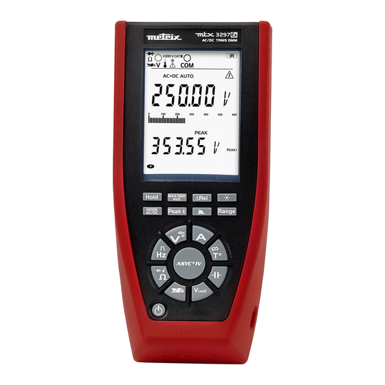
- Page 1 EN - User’s manual MTX 3297Ex Intrinsically Safe Digital Multimeter Portable multimeter with digital display...
- Page 2 Thank you for purchasing this Portable multimeter MTX 3297Ex with digital display. For best results from your instrument: „ read these operating instructions carefully, „ comply with the precautions for use. Failure to observe these warnings and/or directions may damage the instrument and/or its components and may endanger the user.
-
Page 3: Table Of Contents
2.5. Maintenance ................................7 2.6. Replacing the fuse ...............................8 2.7. Batteries ..................................8 2.8. Active communication interface ...........................8 3. DESCRIPTION OF THE INSTRUMENT ..........................9 3.1. MTX 3297EX ................................9 3.2. Display unit ................................10 3.3. Switch ..................................12 3.4. Keypad ..................................13 3.5. Connection ................................15 4. GETTING STARTED ................................16 4.1. - Page 4 7.19. Operation of the audible beep ..........................44 7.20. Variation in the nominal range of use ........................44 7.21. Response of the filter ...............................45 8. CHARACTERISTICS OF THE MTX 3297EX (EXPLOSIVE ZONE) ................46 9. GENERAL CHARACTERISTICS ............................46 9.1. Environmental conditions ............................46 9.2. Power supply ................................46 9.3.
-
Page 5: Delivery Condition
1. DELIVERY CONDITION ❶ 1.1. UNPACKING ❹ ❻ ATTESTATION DE VERIFICATION CHECKING ATTESTATION 190, rue Championnet Numéro de l'appareil : 75876 PARIS Cedex 18 Equipment number FRANCE Type / Model Désignation de l'instrument : Instrument designation ❺ Vérifié par : Signature : Tested by Signature... -
Page 6: General Instructions
This multimeter is compliant with safety standard IEC 61010-2-033, concerning multimeters. 2.2. PRECAUTIONS AND SAFETY MEASURES This manual concerns only the use of the MTX 3297Ex in a safe, non-explosive zone. „ This instrument is disigned for used: „ indoor „... -
Page 7: Special Functions
2.2.4. FEATURES PROTECTING THE MEASUREMENT INPUTS „ This multimeter has several features to protect them: „ varistor protection that clips transient voltage surges on the measurement terminals. „ PTC (Positive Temperature Coefficient) protection against permanent overvoltages less than or equal to 1 000 V during resistance, capacitance, and diode test measurements. -
Page 8: Replacing The Fuse
2.8. ACTIVE COMMUNICATION INTERFACE The multimeter can communicate with a PC via the USB link. The MTX 3297Ex includes a USB link using an isolated optical USB cord (in option) and SX-DMM software, plus Labview and Labwindows drivers to program the devices. -
Page 9: Description Of The Instrument
3. DESCRIPTION OF THE INSTRUMENT 3.1. MTX 3297EX 3.1.1. FRONT AND BACK PANEL 3.1.2. PROP 3.1.3. TERMINAL BLOCK Optical connector: active only outside EX environment... -
Page 10: Display Unit
3.2. DISPLAY UNIT The display is in two parts: „ A digital display for convenient reading of the digits: - main display unit: 12.7 mm - secondary display unit: 9.7 mm „ The "bargraph" display (61 segments) with scale (indication of the measurement range) for an analogue reading. 3.2.1. - Page 11 3.2.3. TABLE OF SYMBOLS DISPLAYED ON THE SCREEN Symbols Designation Measurement of the AC signal Measurement of the DC signal AC+DC Measurement of the AC and DC signal AUTO Automatic range switching Δ REL Values relative to a reference Reference value HOLD Storage and display of stored values MAX MIN AVG...
-
Page 12: Switch
COM measurement input Ampere measurement input 1 000 V CAT III Input indication Isolated optical link (USB) input Display of unit on the main display unit (2x14 segments) Display of unit on the secondary display unit (2x14 segments) Identifies the reminder of the display zone connection (*) When voltages exceeding 60 V or 25 V are measured, the... -
Page 13: Keypad
3.3.1. KEYS OF THE SWITCH Short press Successive short press Current measurement Temperature measurement Sélection du type de sonde : Pt 100, Pt 1000 Capacitance measurement Low-impedance AC voltage measure- ment (VLowZ) Current and frequency measurement Selection of the transformation ratios 1, 10, 100, 1,000 mV/A with a clamp-on ammeter Resistance measurement, audible Selection of the continuity, diode functions... - Page 14 3.4.1. FUNCTION KEYS Successive short presses Long press Activation/deactivation of storage of the measurements and of the quantities at a given time: - Hold of the display without stopping the acquisitions. The - Hold of the display after stabilization bargraph continues to operate normally. of the measurement (Auto HOLD) - Exit from the HOLD mode - Exit from the Auto HOLD mode...
-
Page 15: Connection
Activation of the relative display mode: - Display and storage of the reference and differential values in the unit of the quantity measured. - 1st press: activates the relative mode ∆REL (present value - reference value) Exit from the ∆REL mode and stores the measured value that will be used as reference. -
Page 16: Getting Started
4.1.2. POWER SUPPLY The MTX 3297Ex is powered only by 4 qualified batteries 1.5 V (Refer to ATEX/IECEx Instructions Manual) Remove the pull tabs from the batteries before the first use: unscrew the 3 cross-headed screws, then remove the battery membrane. -
Page 17: Functional Description
5. FUNCTIONAL DESCRIPTION 5.1. MAX MIN AVG MODE A beep indicates an overshoot or a change of quantity. 5.1.1. DISPLAYS IN THE V FUNCTION AC+DC Measured signal: 230 V, 50 Hz: Main dislay unit Present value of the signal Secondary display unit ... - Page 18 The measured signal changes to 250 V, 50 Hz: h:min:sec Ex.: 27 s MAX value Momentary screen (4s) indicating the time-stamped max. value, if the value changes or if the value is looked up. The display then becomes: ...
-
Page 19: Peak Mode
The display then becomes: Present value of the signal MIN value 5.1.4. FOR THE AVG VALUE press Present value of the signal AVG value 5.1.5. DE-ACTIVATION By a long press on the key. 5.2. PEAK MODE A beep indicates an overshoot or a change of quantity. - Page 20 5.2.2. FOR THE PEAK+ VALUE press on Present value of the signal Peak+ value 5.2.3. FOR THE PEAK- VALUE press on Present value of the signal Peak- value...
-
Page 21: Δrelative Mode (Principal Reading Only)
5.2.4. DE-ACTIVATION By a long press on the key. 5.3. ΔRELATIVE MODE (PRINCIPAL READING ONLY) 5.3.1. DISPLAYS IN THE V FUNCTION AC+DC Measured signal: 1 V, 100 Hz: Present value of the signal Secondary measurement value 5.3.2. ACTIVATION OF THE ΔREL MODE A short press on ... -
Page 22: Clamp Function
Short press, in the ΔREL mode, on present value - reference value ΔREL (%) = x 100 reference value Reference value key erases the reference value. A long press on the 5.3.3. DE-ACTIVATION By a long press on the key. 5.4. -
Page 23: Serial Operation Of The Keys Of The Switch
5.5. SERIAL OPERATION OF THE KEYS OF THE SWITCH Press 1 Press 2 Press 3 Press 4 Press 5 Press 6 Short press ... ... Pt100 Pt1000 Pt100 Pt1000 Pt100 Pt1000 ... Capa Capa Capa Capa Capa Capa ... -
Page 24: Functions Of The Switch And Keys
5.6. FUNCTIONS OF THE SWITCH AND KEYS , dBm, W, continuity, diode, duty cycle, To access the and pulse duration functions, press the button of the switch corresponding to the chosen function. Here are the possible combinations according to the type of measurement: RANGE MAX/MIN/ Type of measurement... -
Page 25: How Are The Various Quantities Measured
6. HOW ARE THE VARIOUS QUANTITIES MEASURED ? 6.1. VOLTAGE MEASUREMENT AC voltage measurement, or measurement of an AC voltage superposed on a DC voltage, or DC voltage measurement at high impedance. : This position is provided to allow measurements in electrical installations. The input impedance <1 MΩ serves to avoid measuring "phantom"... -
Page 26: Current Measurement
6.2. CURRENT MEASUREMENT 6.2.1. AS AN AMMETER 1. Press: 2. Select the type of signal, AC+DC, AC, or DC, by pressing Depending on what you select, the screen displays AC, DC, or AC+DC. 3. Connect the black lead to the “COM” terminal and the red lead to “A”. If the connection is not correct, an audible beep and a visible signal (LEADS) are activated. -
Page 27: Frequency Measurement
5. Place the clamp arround the conductor: Clamp, V output 7. Read the measurement value indicated on the display unit. The measurement accuracy is indicated in "Technical characteristics", §Clamp". 8. As default, the 2nd display unit indicates the transformation ratio in mV/A. It is possible to activate the filter in A . -
Page 28: Resistance Measurement
6.4. RESISTANCE MEASUREMENT 1. Press the button of the switch: 2. Connect the black lead to the “COM” terminal and the red lead to “V”. 3. Place the test probes on the terminals of the component. Resistance measurements must be made with power off. However, while the presence of a voltage will prevent or throw off the measurement, it will not damage the instrument. -
Page 29: Capacitance Measurement (Discharged)
5. Read the measured threshold voltage of the junction indicated on the display unit. 6. "O.L" is displayed, if the circuit is open or the threshold of the diode > 3 V. 6.7. CAPACITANCE MEASUREMENT (discharged) 1. Press: 2. Connect the black lead to the “COM” terminal and the red lead to “V”. 3. -
Page 30: Measurement On An Mli Type Speed Variator
4. Connect the adapter of the Pt100 or Pt1000 temperature probe (*) to the "COM" and "V" terminals, making sure that the polarity is correct. Two-wire Pt100/Pt1000 sensor 5. Read the measurement value indicated on the display unit. If "O.L" is displayed, the probe is open-circuit or short-circuited or the value to be measured exceeds the range. For greater accuracy, avoid exposing the instrument to sudden changes of temperature. - Page 31 5. Place the test probes between two phases of the circuit to be measured: 6. Read the measurement values indicated on the display unit (voltage and frequency). In all cases, "O.L" is displayed above 1 050 V and a beep sounds when the emasurement exceeds 1 000 V. The presence of the symbol indicates that the 300 Hz filter is active.
-
Page 32: Resistive Power
6. Read the measurement value indicated on the display unit. “O.L” is displayed, if I > 20 A. The presence of the symbol indicates that the filter is active. It is very important to leave the filter activated to measure the voltage and frequency of the signal without being perturbed by the MLI. -
Page 33: Dbm Power Ratio In Decibels
6.11. DBM POWER RATIO IN DECIBELS 1. Press 2. Press again. 3. Press to select the reference resistance, 50, 75, 90, or 600 Ohm. 4. Connect the black lead to the “COM” terminal and the red lead to “A”. 5. Place the test probes on the terminals of the circuit to be measured: Connect the instrument as for a voltage measurement. -
Page 34: Calibration Kit (Optional)
2. Install the USB driver on your PC (included in the SX-DMM software). Interface cable Insulated optical connector Communication between MTX 3297Ex and PC in safe zone only. 6.12.2. INSTALLING THE "SX-DMM" SOFTWARE 1. Install the "SX-DMM" software on the PC. -
Page 35: Technical Characteristics (Safe Zone)
7. TECHNICAL CHARACTERISTICS (safe zone) Accuracy: “a% R +b D” means “a% of the reading +b Digit”. Only values with tolerances or limits are guaranteed values. Values without tolerances are given for guidance (standard NFC42670). The technical specifications are guaranteed only after 30 minutes of warming up. Except as otherwise indicated, they are valid from 10 % to 100 % of the measurement range. -
Page 36: Vlowz Ac Rms
1) See the typical curve of the 300 Hz filter. 2) This range is accessible only with the Range key. Input impedance: approx. 10.6 MΩ//50 pF 3) The LCD indicates “+OL” above +1,050 V, “-OL” above -1,050 V or 1,050 VRMS 4) From 1kHz measurement must exceed 15 % of the range. -
Page 37: Currents
7.5. CURRENTS Three possible modes: DC, AC, AC+DC In DC mode, you can measure a direct current or the DC component of an alternating current In the AC and AC+DC modes, you can measure the true RMS (TRMS) value of an alternating current with/without its direct component (no capacitive coupling in “DC”... - Page 38 7.5.2. AAC RMS CURRENT Specified Uncertainty Range Operating range measurement Resolution 40 Hz to 20 Peak factor Voltage drop Protection range kHz (±) (**) 1% L + [0.15% 600 µA 0 to 600.00 µA 60 to 600.00 µA 0.01 µA x (FkHz-1)] 2.6 @ 500 µA 10 mV / µA...
-
Page 39: Frequency
7.6. FREQUENCY 7.6.1. MAIN FREQUENCY MEASUREMENT In this setting, you can measure the frequency of a voltage. Particular reference conditions: 150 mV < U < 600 V When the switch is set to Hz, the 300 Hz filter is not in service. Protection: 1 414 Vpk Specified Range... -
Page 40: Capacity
7.8. CAPACITY 7.8.1. CAPACITANCE METER In this setting, the user can measure the capacitance of capacitor. Specified Measurement Measurement Range Operating range measurement Resolution Intrinsic error current time range 6 nF 0.100 to 6.000 nF 0.100 to 6.000 nF 0.001 nF 2 % L ±... - Page 41 7.11.1. DC CURRENT Ratio / Range 600 mA 60 A 600 A 6 000 A Resolution 0.01 A 0.1 A 1 mV/A Accuracy 0.5 % L ± 2 D 0.5 % L ± 2 D 0.05 % L ± 2 D Resolution 0.001 A 0.01 A...
-
Page 42: Temperature
7.11.3. AAC+DC TRMS CURRENT Ratio / Range 600 mA 60 A 600 A 6 000 A Resolution 0.01 A 0.1 A 0.8 % L + 0.18 % 0.5 % L + 0.18 % x [F(kHz) -1] L x [F(kHz) -1] L 1 mV/A 1.5 % L ±... -
Page 43: W Resistive Power
7.15. W RESISTIVE POWER Display of the resistive power with respect to a reference resistance measured on the installation and saved in memory using the HOLD key (600 Ω is the default) The function determined is: (measured AC+DC voltage) 2/VRef Range AC and AC+DC Resolution... -
Page 44: Operation Of The Audible Beep
7.19. OPERATION OF THE AUDIBLE BEEP Beep reporting a valid key High-pitched sound Beep reporting an invalid key Low-pitched sound Successive beeps reporting an overshoot of the danger threshold (alarm) High-pitched sound Successive beeps reporting recording of the MAX, MIN, PEAK High-pitched sound Successive beeps (alarm) ... -
Page 45: Response Of The Filter
7.21. RESPONSE OF THE FILTER Influence of a sudden change of range (all versions) At 1 kHz and above, during a change of range (except for the 60 V and 600 V ranges), the reaction time of the instrument can be as long as 4 mn for a residual difference of 0.8 %. -
Page 46: Characteristics Of The Mtx 3297Ex (Explosive Zone)
ATEX; along with the safety, control, and adjustment devices, even if they are not in contact with an ATEX, whenever they are necessary for or contribute to the operation of the instruments and protection systems. The MTX 3297Ex multimeter is used in an ATEX zone MTX 3297Ex: Refer to ATEX/IECEx Instructions Manual 9. -
Page 47: Warranty
„ adaptation to a particular application not anticipated in the definition of the equipment or by the user manual „ a shock, a fall, or flooding. The design of the MTX 3297Ex ATEX does not allow any work inside the product. -
Page 48: Mechanical Characteristics
„ HV probe „ CMS clamp „ Multifix adapter for DMM „ USB optical cable „ Carrying case 12.1.1. SPARE MTX 3297Ex: Refer to ATEX/IECEx Instructions Manual List of clamps Ratio set to mV/A Miniflex from 0.5 to 3 000 AAC...
Need help?
Do you have a question about the MTX 3297Ex and is the answer not in the manual?
Questions and answers