Table of Contents
Advertisement
Quick Links
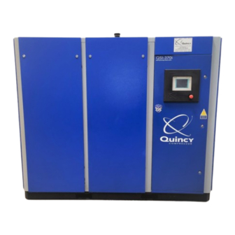
QSI-i Series
50-200 Horsepower
Direct Drive Industrial Air Compressors
Instruction Manual
This manual contains important safety information and should be made available to
all personnel who operate and/or maintain this product. Carefully read this manual
before attempting to operate or perform maintenance on this equipment.
Manual No. 2012203808
February 2015 Edition
Advertisement
Table of Contents
Troubleshooting


Need help?
Do you have a question about the QSI-i Series and is the answer not in the manual?
Questions and answers