Table of Contents
Advertisement
OIL-FREE SCROLL
COMPRESSORS
QOF 2, QOF 3, QOF 5, QOF 7.5
Instruction Manual
This manual contains important safety information and should be made available to
all personnel who operate and/or maintain this product. Carefully read this manual
before attempting to operate or perform maintenance on this equipment.
Manual No. 2920 7150 80
November 2014 Edition
Advertisement
Table of Contents

Related Manuals for Quincy Compressor QOF 2


Summary of Contents for Quincy Compressor QOF 2
- Page 1 OIL-FREE SCROLL COMPRESSORS QOF 2, QOF 3, QOF 5, QOF 7.5 Instruction Manual This manual contains important safety information and should be made available to all personnel who operate and/or maintain this product. Carefully read this manual before attempting to operate or perform maintenance on this equipment. Manual No. 2920 7150 80 November 2014 Edition...
-
Page 3: Table Of Contents
Refrigerant dryer maintenance ..................34 Section VII - Problem solving ..............35-37 Section VIII - Technical data Readings on control panel ....................38 Electric cable size ......................38 Settings for overload relay and fuses ................39 Temperature protection and safety valve settings ............40 Reference conditions and limitations ................41 Compressor data .......................41 Quincy Compressor... - Page 4 Table of Contents Section IX - Instructions for use ..............43 Section X - Guidelines for inspection ............44 Section XI - Pressure equipment directives ..........45 Section XII - Declaration of conformity ............46 Quincy Compressor...
-
Page 5: Section I - General Information
NOTICE! CAUTION! Identifies important installation, operation or maintenance information which is not hazard related. This symbol identifies hot surfaces which could result in personal injury or property damage. Quincy Compressor... - Page 6 • This compressor is designed for use in • Observe control panel displays daily the compression of normal atmospheric to ensure compressor is operating air only. No other gases, vapors or properly. fumes should be exposed to the • Follow all maintenance procedures and compressor intake, nor processed check all safety devices on schedule. through the compressor. • Never disconnect or tamper with the • Relieve all pressure internal to the high air temperature (HAT) sensors. compressor prior to servicing. Do not depend on check valves to hold system • Compressed air is dangerous, do not pressure. play with it. Quincy Compressor...
- Page 7 This manual may not be appropriate in those cases. Spare Parts Ordering Information Serial/Model Identification Plate Quincy Compressor maintains replacement parts for Quincy compressors and accessories. A repair parts list is shipped with all new machines. Order parts from your Authorized Quincy distributor. Use only genuine Quincy replacement parts.
- Page 8 Section I - General Information Warranty Quincy Compressor® Industrial Scroll Products QOF (2-30 horsepower ONLY) Belt Drive Compressors (Operating at 145 PSIG full load pressure or less) Standard Warranty Quincy Compressor (Seller) warrants products of its own manufacture against defects in workmanship and materials under normal use and service, as follows: Packaged Compressors - Twelve (12) months from date of start-up or eighteen (18) months from date of shipment from the factory, whichever occurs first. Quincy Compressor...
-
Page 9: Section Ii - Description
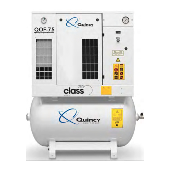
General QOF-2, QOF-3, QOF-5, QOF-7.5 are stationary, single stage, oil-free compressors, driven by an electric motor. The compressors are controlled by a pressure switch. The compressors are enclosed in a sound dampening enclosure and are air cooled. Available versions: • The basic version (QOF) comprises the motor, the compressor element, an air cooled aftercooler and the regulation and protection components. • The QOF with dryer is a QOF, completed with an integrated refrigerant dryer. The basic version (referred to as the floor mounted version (FM)) does not include an air receiver. An air receiver is available as option. Available options: • Air receiver of 30 l (7.93 US gal), 270 l (71.3 US gal) or 500 l (132 US gal). The 30 l receiver consists of a module with three 10 l (2.64 US gal) receivers. The 30 l receiver option includes an electronic drain. • Receiver mounted version (270 l and 500 l): electronic drain on the air receiver • Floor mounted compressors without refrigerant dryer: water separator on the outlet • Prefilter mats on the air inlet • Phase sequence relay (on 3-phase units) The control panel comprises a pressure gauge, an hour meter and a start button. The compressor is controlled by a pressure switch (PS). The electric components are located in the cubicle behind the front panel door. A check valve (CV) prevents loss of compressed air when the compressor is stopped. A temperature switch and a safety valve (SV) protect the compressor element against overheating and too high pressure respectively. The compressed air is cooled by an air cooler (Ca). Single phase units are equipped with a vent valve for easy starting. Quincy Compressor... - Page 10 Section II - Description QOF 5 floor mounted - general view QOF 5 with integrated air receivers (3 x 10 l)- general view Quincy Compressor...
- Page 11 QOF 5 floor mounted - details Inlet air filter Outlet valve Air cooler Compressor element Motor Pressure switch Safety valve TSHH Temperature switch Check valve QOF with dryer The QOF with dryer consists of an QOF, completed with an integrated refrigerant dryer. The control panel comprises a pressure gauge, an hour meter, a start button and a temperature gauge indicating the dew point. The compressor is controlled by a pressure switch (PS). The electric components are located in the cubicle behind the front panel door. A check valve (CV) prevents loss of compressed air when the compressor is stopped. A temperature switch and a safety valve (SV) protect the compressor element against overheating and too high pressure respectively. The compressed air is cooled by an air cooler (Ca) before it enters the dryer. Single phase units are equipped with a vent valve for easy starting. Quincy Compressor...
- Page 12 Section II - Description QOF 5 with dryer on a 270 l receiver - general view Pressure gauge Q1/H1 On/off switch with lamp Hour meter Outlet valve Manual drain valve Automatic drain outlet Dew point gauge Refrigerant dryer QOF 7.5 with dryer - details Quincy Compressor...
- Page 13 Section II - Description Inlet air filter Outlet valve Air cooler Compressor element Motor Check valve Safety valve Manual drain valve Refrigerant dryer TSHH Temperature switch Flow diagram Flow diagram Quincy Compressor...
- Page 14 Compressed air outlet Air flow Air is drawn through air filter (100) and is compressed by the compressor element (101). Next, the compressed air flows through the check valve (105) and the air cooler (106). Single phase units are equipped with a solenoid valve (109) and a silencer (110) for easy starting at low voltage. On floor mounted versions without refrigerant dryer, the air flows then directly to the outlet valve (121). On receiver mounted units, the compressed air flows into the air receiver (120), onto which the outlet valve AV (121) is fitted. On compressors with refrigerant dryer, the compressed air flows to the refrigerant dryer (ID), where the water vapor condensates by cooling down. The water is removed via the integrated water separator (201c) and the electronic drain (210). For details on the operation of the ID dryer, see section Refrigerant dryer. Cooling The compressor element (101) is cooled by an integrated radial fan (102). An axial fan (107) fitted on the motor shaft provides cooling air for the air cooler (106). On compressors with integrated refrigerant dryer, a separate fan (204) delivers cooling air for the dryer. Condensate management Floor mounted compressors without refrigerant dryer have no drain. A water separator is available as option. The dryer of compressors equipped with a refrigerant dryer has an integrated water separator (201c) and an electronic water drain (210). The water separator has a manual drain valve (211) and a connection for the automatic drain. For more details, consult section Refrigerant dryer. The receiver of receiver mounted compressors has a manual drain valve (122) at the bottom. An electronic Quincy Compressor...
- Page 15 Compressed air enters heat exchanger (1) and is cooled by the outgoing, cold, dried air. Water in the incoming air starts to condense. The air then flows through the evaporator heat exchanger (2) where the refrigerant evaporates, causing the compressed air to be cooled further to close to the evaporating temperature of the refrigerant. More water in the air condenses. The cold air then flows through water separator (3), where the condensate is separated from the air. The condensate is automatically drained by the electronic condensate drain (9). The cold, dried air flows through heat exchanger (1) where it is warmed up by the incoming air. Quincy Compressor...
- Page 16 Electronic condensate drain The dryer is equipped with an electronic condensate drain. The condensate, separated by the condensate trap, accumulates inside the drain. Once the condensate reaches a certain level, it is discharged through the drain outlet (1). The condensate can also be drained by pressing the test button (2). The drain filter can be cleaned by opening the manual drain valve (3), see section reventive Maintenance schedule. Quincy Compressor...
-
Page 17: Section Iii - Installation
Section III - Installation • Dimension drawings • Installation proposal • Electrical connections • Pictographs Dimension drawings The dimension drawings are available in pdf format on the CD Rom, supplied with the compressor. Installation proposal Quincy Compressor... - Page 18 = required ventilation capacity in m N = shaft input of the compressor in kW Δt = temperature increase in the compressor room in °C 4. Air receiver: an optional air receiver can be necessary to limit the cycle frequency. Recommended maximum is 20 starts per hour. 5. Optional filters can be installed in the pressure line downstream the air outlet valve, e.g.: • A DD filter for general purpose filtration. The filter traps solid particles down to 1 micron. • A PD filter for filtration down to 0.01 micron. A PD filter must always be installed downstream a DD filter. 6. Control cubicle with monitoring panel. 7. Compressor and dryer cooling air outlet Quincy Compressor...
- Page 19 The installation must be earthed and protected by fuses in each phase. Install an isolating switch near the compressor. Make sure that this switch is open to isolate the compressor from the mains before carrying out any connection. Supply cable Consult section Cable size for the section of the power supply cable. An electric cable is provided on the unit. Fit a suitable plug on the cable. Plug in the cable. Three voltage units The compressors leave the factory wired for 230 V. If the compressor is to be used on 460 V, rewire the motor as follows: 1. Take all necessary precautions. 2. Change the connection in the motor terminal box according following instructions: • For QOF 3 and QOF 5: Quincy Compressor...
-
Page 20: Pictographs
Section III - Installation • For QOF 7.5: 3. Change also the voltage connection on auxiliary transformer T1. 4. Replace the fuses. 5. Adjust the overload relay settings (see section Settings of overload relay and fuses. Pictographs Pictographs Reference Designation Warning: the compressor starts and stops automatically. Do not perform service when pressurized and when the voltage is on. Read the instruction book, switch off the power and depressurize the compressor before maintenance or repair. Warning: when the voltage is on, the unit can start and stop automatically. Warning: rotating fan. Quincy Compressor... - Page 21 Section III - Installation Warning: supply voltage. Warning: hot surface. Do not adjust the pressure switch while it is depressurized , because this can dam- age the switch (only for compressors controlled by a pressure switch). Warning: rotating fan. Warning: safety valve blowing. Warning: rotating fan. Warning: belts. Warning: before connecting compressor electrically, consult Instruction book for motor rotation direction. Quincy Compressor...
-
Page 22: Section Iv - Operation
4. Close the condensate drain valve(s). See sections Introduction and Flow diagram for their location. 5. Switch on the voltage. Lamp (H1) alights. Start the compressor and stop it immediately by means of switch Q1 (see section Quincy Compressor... -
Page 23: Starting
A compressor equipped with a phase sequence relay will not start if the phase sequence is wrong. In that case, reverse two incoming electric lines to solve the issue. Starting Control panel Quincy Compressor... -
Page 24: During Operation
(specially in case of compressors without dryer). See also section Preventive Maintenance schedule). NOTICE! The dew point will deviate from nominal when the nominal conditions are exceeded. If the dew point remains too high or unstable, consult section Problem solving. Stopping Control panel Quincy Compressor... -
Page 25: Taking Out Of Operation
1. Stop the compressor and close the air outlet valve. 2. Switch off the voltage and disconnect the compressor from the mains. 3. Depressurise the compressor. On compressors with refrigerant dryer and on compressors with an air receiver, open the manual drain valve(s) (Dm / Dm1). 4. If provided, shut off and depressurize the part of the air net which is connected to the outlet valve. Disconnect the compressor from the air net. 5. If provided, disconnect the compressor condensate piping from the local condensate drain system. Quincy Compressor... -
Page 26: Section V - Preventive Maintenance
The longer interval checks and actions must also include the shorter interval checks. Preventive maintenance schedule Period Running Operation (note 1) hours (note 1) Daily • Check readings on the display. • Compressors with integrated air receiver and/or compressors with integrated refrigerant dryer: Check if condensate is discharged regularly. • Receiver mounted compressors: Drain the condensate manually at the end of the day. • Compressors with integrated dryer: Check the dew point. Every 3 Inspect the air inlet filter(s) (AF). months Inspect the prefilter mats on the cooling air intake openings (if (note 2) fitted). Check for cleanness and damage. Clean if dirty, replace if damaged. Clean the compressor and check the air cooler . If necessary, clean by air jet. Quincy Compressor... - Page 27 Every 2 5000 10 bar and 145 psi compressors: years • Replace the element outlet pipe and the plastic insert. See section Outlet pipe replacement. (Only on QOF 2, QOF 3 and QOF 5). • Clean fan (FN1 - see Flow diagram), fan duct and element cooling fins (see note 2). • Have orbiting scroll bearing and pin crank bearings greased (see note 3). • Replace tip seals and dust seal (see also note 4). Every 4 10000 8 bar and 116 psi compressors: years • Replace the element outlet pipe and the plastic insert. See section Outlet pipe replacement. (Only on QOF 2, QOF 3 and QOF 5). • Clean fan (FN1 - see Flow diagram), fan duct and element cooling fins (see note 2). • Have orbiting scroll bearing and pin crank bearings greased (see note 3). • Replace tip seals and dust seal (see also note 4). Quincy Compressor...
- Page 28 Electronic components are subject to the EU Directive 2002/96/EC for Waste Electrical and Electronic Equipment (WEEE). As such, these parts must not be disposed of at a municipal waste collection point. Refer to local regulations for directions on how to dispose of this product in an environmental friendly manner. Quincy Compressor...
-
Page 29: Section Vi - Adjustments And Servicing Procedures
• Replacement of the outlet pipe • Refrigerant dryer maintenance Pressure switch Description The pressure switch (PS - See section Flow diagram) determines the operating pressure of the compressor. The stopping and starting pressures are the opening and closing pressures of the switch. NOTICE! Adjustments may only be carried out when the switch is pressurized. Pressure switch The stopping pressure is controlled by adjusting screw (2). Turn the screw clockwise to raise the stopping pressure, anti-clockwise to lower it. The pressure difference between starting and stopping is adjusted by means of adjusting screw (1). Turn the screw anti-clockwise to reduce the pressure difference, clockwise to increase it. Quincy Compressor... - Page 30 Section VI - Adjustments and servicing procedures Adjustment range Example: Stopping pressure: 7 bar(e) (100 psig) Starting pressure: adjustable between 5.8 bar(e) (84 psig) and 3 bar(e) (43.5 psig) 8 bar (116 psi) units: the pressure switch is factory-adjusted to start the compressor at 6.5 bar(e) (94 psig) and to stop at 7.75 bar(e) (112 psig). 10 bar (145 psi) units: the pressure switch is factory-adjusted to start the compressor at 8 bar(e) (116 psig) and to stop at 9.75 bar(e) (141 psig). Quincy Compressor...
- Page 31 Air cooler Cleaning Keep the cooler clean to maintain cooling efficiency. If necessary, remove any dirt with a fibre brush. Never use a wire brush or metal objects. Next, clean by air jet in reverse direction of normal flow. If it is necessary to wash the cooler with a cleansing agent, consult your supplier. Drive motor Instructions The motor bearings are greased for life and do not require special attention. Keep the motor free from dust for optimal cooling. Safety valve Testing NOTICE! Testing shall only be carried out by competent personnel 1. Stop the compressor, close the air outlet valve and switch off the voltage. Quincy Compressor...
- Page 32 If more than one belt is used, the belts must be replaced as a set, even if only one of them seems worn. Use genuine spare parts belts only. The number of the belt set is mentioned in the Parts list. 1. Remove the service panel (S). 2. Loosen screw (A). Quincy Compressor...
- Page 33 Section VI - Adjustments and servicing procedures 3. Remove the front panel. 4. Remove the inlet baffle (I). 5. Loosen screws (B). 6. Loosen screw (C). 7. Use slot (D) to lift the motor plate. 8. Install the new belt(s) in the pulley grooves. Quincy Compressor...
- Page 34 Cleaning the compressor element CAUTION! • Compressor element cooling channels can be hot when the compressor has just been turned off. • Do not clean the cooling channels with organic solvent since this will damage the surface treatment. Quincy Compressor...
- Page 35 Procedure: 1. Stop the compressor and switch off the power. 2. Close the air outlet valve and depressurise the compressor. 3. Remove the fan duct: • Unscrew the 3 bolts (1). • Remove clip (2) (if applicable). • Remove fan duct (3). 4. Clean cooling channels: • Remove dust from the cooling channels (1) by means of air jet (see next figure). • Clean the fan duct (2). 5. Reassemble the fan duct: • Put the fan duct in place. • Fit the 3 bolts and the clip. The unit is now again ready for use. Quincy Compressor...
- Page 36 Section VI - Adjustments and servicing procedures Replacement of the outlet pipe (only applicable to QOF 2, QOF 3 and QOF 5) Description The scroll element outlet pipe (1) contains a plastic insert (3). Due to the heat of the compressed air, the plastic insert can become brittle. Therefore it is recommended to replace the outlet pipe together with the insert when that is the case. Both parts are available as a kit (outlet pipe set). See the Spare Parts List for part number. The outlet pipe set contains two parts: • The plastic insert (3) • The metal outlet pipe (1) Procedure 1. Stop the compressor, depressurize and switch off the voltage. 2. Loosen the coupling (3) while fixating the nipple (2) with a spanner. 3. Remove the outlet pipe together with the nipple 4. Fit the nipple to the new outlet pipe and tighten. Use only PTFE tape. 5. Fit the plastic insert in place as indicated on the drawing and assemble the outlet pipe with a maximum torque of 10 Nm (7.4 lbf.ft) plus maximum one turn (360°).
- Page 37 Cleaning of the drain filter can be done by opening the manual drain valve during a few seconds. Device settings The regulating and safety devices are factory adjusted to obtain optimum performance of the dryer. Do not alter the setting of any of the devices. CAUTION! Connecting pressure measuring devices in the refrigerant circuit can change the amount of refrigerant in the system. This results in a less optimal working of the dryer. Quincy Compressor...
-
Page 38: Section Vii - Problem Solving
Air consumption exceeds Check equipment connected. capacity of compressor. Remove and check filter. Choked air filter Replace if necessary. Compressor capacity or Safety valve leaking Replace valve. pressure below Check condition of belts and normal Drive belts slipping. belt tension. Correct or replace as required. Compressor element out of Consult the supplier. order Quincy Compressor... - Page 39 Condenser pressure too high or See below too low Evaporator Have circuit repaired or pressure is too Shortage of refrigerant recharged high or too low Hot gas bypass valve incorrectly Have the valve adjusted or set or out of order replaced Quincy Compressor...
-
Page 40: Section Vii - Problem Solving
Automatic drain out of order discharging air an Replace as necessary water Clean the filter of the automatic Electronic drain by opening the manual condensate drain Drain system clogged drain valve. Check functioning inoperative of the drain by pushing the test button. Quincy Compressor... -
Page 41: Section Viii - Technical Data
The voltage drop must not exceed 5% of the nominal voltage. It may be necessary to use cables of a larger size than those stated to comply with this requirement. Cable size QOF 2 QOF 3 QOF 5 QOF 7.5... - Page 42 Section VIII - Technical data QOF 2 QOF 3 QOF 5 QOF 7.5 Frequency Voltage Cable size Cable size Cable size Cable size 50 Hz 230 V 3~ 4 mm 6 mm 6 mm 50 Hz 400 V 3~ 1.5 mm 1.5 mm 2.5 mm 50 Hz 400 V 3~ + N 1.5 mm 1.5 mm 2.5 mm UL/CUL 60 Hz...
- Page 43 Compressor element outlet temperature Opens at Reference QOF 2 (8 bar / 116 psi) 70 °C (158 °F) TDS1 QOF 2 (10 bar / 145 psi) 80° C (176 °F) TSD1 QOF 3 (8 bar and 10 bar / 116 and 145 psi) 70 °C (158 °F) TSD1 QOF 5 (8 bar and 10 bar / 116 and 145 psi) 70 °C (158 °F) TSD1 QOF 7.5 (8 bar and 10 bar / 116 and 145 psi) 200 °C (392 °F) TSD2 Safety valve Pressure version Set pressure Unit Reference 8 bar compressors bar(e) 116 psi compressors psi(g) 10 bar compressors bar(e) 145 psi compressors psi(g) Quincy Compressor...
-
Page 44: Compressor Data
˚C Minimum ambient temperature ˚F Compressor data NOTICE! All data specified below apply under reference conditions, see section Reference conditions and limitations. Compressor type QOF 2 QOF 2 QOF 3 QOF 3 8 bar 10 bar 8 bar 10 bar... - Page 45 Section VIII - Technical data Compressor type QOF 2 QOF 2 QOF 3 QOF 3 8 bar 10 bar 8 bar 10 bar 116 psi 145 psi 116 psi 145 psi Nominal motor power Nominal motor power Sound pressure level dB(A) Refrigerant type (Full-Feature) R134a R134a...
-
Page 46: Section Ix - Instructions For Use
(part of the documentation delivered with the unit). Lifetime of the air receiver mainly depends on the working environment. Avoid installing the compressor in a dirty and corrosive environment, as this can reduce the vessel lifetime dramatically. Do not anchor the vessel or attached components directly to the ground or fixed structures. Fit the pressure vessel with vibration dampers to avoid possible fatigue failure caused by vibration of the vessel during use. Use the vessel within the pressure and temperature limits stated on the nameplate and the testing report. No alterations must be made to this vessel by welding, drilling or other mechanical methods. Quincy Compressor... -
Page 47: Section X - Guidelines For Inspection
Section X - Guidelines for inspection Guidelines On the Declaration of Conformity / Declaration by the Manufacturer, the harmonised and/or other standards that have been used for the design are shown and/or referred to. The Declaration of Conformity / Declaration by the Manufacturer is part of the documentation that is supplied with this compressor. Local legal requirements and/or use outside the limits and/or conditions as specified by the manufacturer may require other inspection periods as mentioned below. Quincy Compressor... -
Page 48: Section Xi - Pressure Equipment Directives
Section XI - Pressure equipment directives Components subject to 97/23/EC Pressure Equipment Directive Components subject to 97/23/EC Pressure Equipment Directive greater than or equal to category II Pressure version Part number Description PED Class 8 bar 0830 1008 54 Safety valve 116 psi 0830 1008 49 Safety valve 10 bar 0830 1007 68 Safety valve 145 psi 0830 1008 35 Safety valve Overall rating The compressors conform to PED smaller than category I. Quincy Compressor... -
Page 49: Section Xii - Declaration Of Conformity
Section XII - Declaration of conformity Typical example of a Declaration of Conformity document (1): Contact address: International Compressor Distribution NV Boomsesteenweg 957 B-2610 Wilrijk (Antwerp) Belgium Quincy Compressor... - Page 50 Section XII - Declaration of conformity On the Declaration of Conformity / Declaration by the Manufacturer, the harmonised and/or other standards that have been used for the design are shown and/or referred to. The Declaration of Conformity / Declaration by the Manufacturer is part of the documentation that is supplied with this device. Quincy Compressor...
- Page 51 Seller is not responsible for loss or damage in transit after having received “In Good Order” receipt from the carrier. All claims for loss or damage in transit should be made to the carrier. Quincy Compressor...
- Page 52 ENVIRONMENTAL AND OSHA REQUIREMENTS: At the time of shipment of the equipment from the factory, Quincy Compressor / Ortman Fluid Power will comply with the various Federal, State and local laws and regulations concerning occupational health and safety and pollution. However, in the installation...
- Page 53 Notes ____________________________________________________________________ ____________________________________________________________________ ____________________________________________________________________ ____________________________________________________________________ ____________________________________________________________________ ____________________________________________________________________ ____________________________________________________________________ ____________________________________________________________________ ____________________________________________________________________ ____________________________________________________________________ ____________________________________________________________________ ____________________________________________________________________ ____________________________________________________________________ ____________________________________________________________________ ____________________________________________________________________ ____________________________________________________________________ ____________________________________________________________________ ____________________________________________________________________ ____________________________________________________________________ ____________________________________________________________________ ____________________________________________________________________ ____________________________________________________________________ ____________________________________________________________________ ____________________________________________________________________ ____________________________________________________________________ ____________________________________________________________________ ____________________________________________________________________ ____________________________________________________________________ ____________________________________________________________________ ____________________________________________________________________ ____________________________________________________________________ ____________________________________________________________________ ____________________________________________________________________ ____________________________________________________________________ ____________________________________________________________________ Quincy Compressor...
- Page 54 Notes ____________________________________________________________________ ____________________________________________________________________ ____________________________________________________________________ ____________________________________________________________________ ____________________________________________________________________ ____________________________________________________________________ ____________________________________________________________________ ____________________________________________________________________ ____________________________________________________________________ ____________________________________________________________________ ____________________________________________________________________ ____________________________________________________________________ ____________________________________________________________________ ____________________________________________________________________ ____________________________________________________________________ ____________________________________________________________________ ____________________________________________________________________ ____________________________________________________________________ ____________________________________________________________________ ____________________________________________________________________ ____________________________________________________________________ ____________________________________________________________________ ____________________________________________________________________ ____________________________________________________________________ ____________________________________________________________________ ____________________________________________________________________ ____________________________________________________________________ ____________________________________________________________________ ____________________________________________________________________ ____________________________________________________________________ ____________________________________________________________________ ____________________________________________________________________ ____________________________________________________________________ ____________________________________________________________________ ____________________________________________________________________ Quincy Compressor...
- Page 56 Quincy Compressor Products: 251.937.5900 © 2012 Quincy Compressor E-mail: info@quincycompressor.com All Rights Reserved. Litho in U.S.A. Website: www.quincycompressor.com...
Need help?
Do you have a question about the QOF 2 and is the answer not in the manual?
Questions and answers