halstrup-walcher PS 3 EC-STO Series Instruction Manual
Hide thumbs
Also See for PS 3 EC-STO Series:
- Instruction manual (67 pages) ,
- Original instruction manual (47 pages) ,
- Manual (32 pages)

Related Manuals for halstrup-walcher PS 3 EC-STO Series


Summary of Contents for halstrup-walcher PS 3 EC-STO Series
- Page 1 Instruction Manual PSx3xxEC-STO halstrup-walcher GmbH Stegener Straße 10 D-79199 Kirchzarten Phone: +49 (0) 76 61/39 63–0 E-Mail: info@halstrup-walcher.com Internet: www.halstrup-walcher.com Document 7100.006704...
-
Page 2: Revision Overview
PSE 335-14 - EC - Z - 0 - Z - 65 Accessories PSx3xxEC-STO series We offer you the corresponding supply and data plugs for all unit types. Please contact our sales department, stating the complete type designation, at the following e-mail address Vertrieb@halstrup-walcher.de... - Page 3 Instruction Manual PSx3xxEC-STO...
-
Page 4: Purpose Of Instruction Manual
Instruction Manual PSx3xxEC-STO Purpose of instruction manual This instruction manual describes the features of the PSx3xx positioning system and provides guidelines for its use. Every person who is tasked with carrying out work on or with the appliance must have read and understood the operating instructions before starting work on the appliance. -
Page 5: Table Of Contents
Instruction Manual PSx3xxEC-STO Table of Contents Revision Overview ....................... 2 Accessories PSx3xxEC-STO series ..................2 Purpose of instruction manual .................... 4 Conformity ..........................4 Table of Contents ......................... 5 Safety precautions ..................... 7 Qualified personnel ....................7 Explanation of symbols ..................7 Appropriate use .................... - Page 6 Instruction Manual PSx3xxEC-STO Use of the “Upper mapping end” parameter ............43 5.6.1 Delivery state ..................... 43 5.6.2 Shifting the positioning range upwards starting from the delivery state ....44 5.6.3 Shifting the positioning range downwards starting from the delivery state ..45 5.6.4 Shifting the positioning range depending on the actual position ......
-
Page 7: Safety Precautions
Instruction Manual PSx3xxEC-STO Safety precautions This section provides an overview of all the important safety aspects for optimum protection of personnel and for safe and trouble-free operation. 1.1 Qualified personnel These operating instructions are intended for qualified electricians and fitters who are authorized to install, electrically connect, commission and label devices and systems in accordance with safety standards, as well as for the operator and manufacturer of the system on which the drives are installed. -
Page 8: Appropriate Use
Instruction Manual PSx3xxEC-STO 1.3 Appropriate use Positioning systems are especially suitable for automatically setting tools, stops or spindles for wood-processing equipment, packing lines, printing equipment, filling units and other types of special machines. PSx3xx positioning systems are not stand-alone devices and may only be used if coupled to another machine. -
Page 9: Inappropriate Use
Instruction Manual PSx3xxEC-STO 1.4 Inappropriate use The use of the positioning devices outside of the operating conditions and technical data and specifications described in the documentation is considered “improper”. The drives are designed for intended operation under normal ambient conditions (according to EN / IEC / UL 61010-1), with the exception of an extended temperature range. -
Page 10: Limitation Of Liability
Instruction Manual PSx3xxEC-STO 1.5 Limitation of liability The device may only be operated in accordance with these operating instructions. All information and instructions in these operating instructions have been compiled taking into account the applicable standards and regulations, the state of the art and our many years of experience and knowledge. -
Page 11: Product Labeling
Instruction Manual PSx3xxEC-STO 1.7 Product labeling Warning symbol Meaning Reference to further documentation Read the operating instructions and safety instructions before transportation, installation or commissioning Warning of hot surface The appliance can become very hot during operation. Temperatures of over 70°C can occur. In the event of a fault, internal components may be overloaded. -
Page 12: Device Description
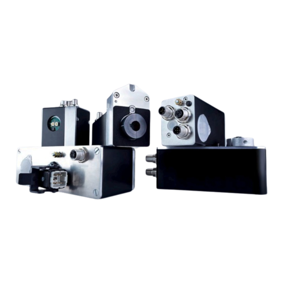
Instruction Manual PSx3xxEC-STO Device description 2.1 Features The PSx3xx positioning system, an intelligent, compact, complete solution for positioning auxiliary and positioning axes, consists of an EC motor, gear power amplifier, control electronics, absolute measuring system and EtherCAT interface. The integrated absolute measuring system eliminates the need for a time-consuming reference run. -
Page 13: Installation
Instruction Manual PSx3xxEC-STO Installation 3.1 Electrical connection NOTICE The following notes on the power supply should be observed. Minimum cross-sections are required for connection to the power supply. For power cables mounted on the device, use only the cross-sections listed below. In order to minimize voltage drop on longer cables, we always recommend using the largest available cross-section. -
Page 14: Assembly Of The Positioning System
Instruction Manual PSx3xxEC-STO 3.2 Assembly of the positioning system CAUTION The maximum permissible axial and radial forces (see chapter 6.4 Physical data) on the motor shaft must not be exceeded during transportation, installation or operation. CAUTION Take the weight of the device into account when selecting the fastening screws! Tightening torques of the fixing screws according to the screw manufacturer's specifications! WARNING... - Page 15 Instruction Manual PSx3xxEC-STO CAUTION The PSx3xx must have a little gap on all sides when mounted, as it can move axially and/or radially during positioning if the hollow shaft and solid shaft are not 100% aligned. This "staggering" is not a defect of the PSx3xx and also has no influence on the function, as long as it can move freely.
-
Page 16: Solid Shaft
Instruction Manual PSx3xxEC-STO 3.2.2 Solid shaft The PSx3xx is installed on the machine by mounting the drive to the axis to be driven using a coupling and an intermediate flange. CAUTION Under no circumstances may the housing cover be used for the purpose of the transmission of force. -
Page 17: Powering The Device
Instruction Manual PSx3xxEC-STO 3.4 Powering the device CAUTION There is one common power supply for the motor and control unit of the positioning system. It is recommended, to use SELV or PELV power supplies. For the combined motor and control power, use a single fuse with max. 3.5 A for each PSx3xx It is strongly recommended to separate power cables to the PSx3xx from other power cables that might have dangerous voltage. -
Page 18: Round Socket For The Bus (Port 1 And Port 2)
Instruction Manual PSx3xxEC-STO 3.5.2 Round socket for the bus (Port 1 and Port 2) connector pattern assignment type (external top view) 1. TD+ 2. RD+ M12 (D-cod.); 3. TD- 4-pol. 4. RD- NOTICE Due to the use of 4-pin sockets, only four-wire cables should be used. 3.5.3 Hybrid bushing for supply, bus and STO (Hybr) connector pattern assignment... -
Page 19: Leds
Instruction Manual PSx3xxEC-STO 3.7 LEDs The following LEDs are located under the transparent sealing plug: P1/P2: green link LEDs for ports 1 and 2 ECAT: EtherCAT STATUS LED (green/red; see EtherCAT specification) V-Motor: The LED is illuminated yellow when power is available to the motor. Switch and LED configurations: PSx30xEC-STO, PSx31xEC-STO, PSx31xEC-14-STO... -
Page 20: Positioning Sequence
Instruction Manual PSx3xxEC-STO 3.8.1 Positioning sequence - To be able to control the drive with the help of PDOs, it has to be switched to the ESM state “operational”. - Transfer target value: - PDO with control word = 0x14 and desired target value - PDO with control word = 0x10 and target value in SDO #2001 ... -
Page 21: Manual Run
Instruction Manual PSx3xxEC-STO 3.8.2 Manual run - Start manual run (transmit PDO with control word = 0x11 resp. 0x12 or, if pre- operational, transmit SDO #2024 with value 0x11 resp. 0x12): device begins to run - End manual run by clearing the manual run command (transmit PDO with control word = 0x10 or, if pre-operational, transmit SDO #2024 with value 0x10) or by deasserting release (transmit PDO with control word = 0x00 or, if pre-operational, transmit SDO #2024 with value 0x00). -
Page 22: Ethercat Interface With Coe Protocol (Canopen Over Ethercat)
Instruction Manual PSx3xxEC-STO 3.9 EtherCAT interface with CoE protocol (CANopen over EtherCAT) The EtherCAT interface uses the protocol “CANopen over EtherCAT” according ETG1000.6 section 5.6: One send and receive SDO per device • • One asynchron send and receive PDO, active by default Meaning of the LEDs: •... -
Page 23: Table Of Entries Implemented From Object Dictionary
Instruction Manual PSx3xxEC-STO 3.9.1 Table of entries implemented from object dictionary Name Index Function Range of Backu Delivery number value State Device Type 1000 returns a “0” when read Manufacturer 100A denotes the software of the EtherCAT drives; Software when being read the string “PSx3xxIE/ECAT” Version is given back Identity... - Page 24 Instruction Manual PSx3xxEC-STO Name Index Function Range of Backu Delivery number value State positioning 2006 permissible difference between target and 1...100 window actual values for “position reached” bit 16 bit value in 1/100 mm (for a 4mm spindle and default settings of numerator and denominator) The maximum value that can be set changes according to the same factor as the...
- Page 25 Instruction Manual PSx3xxEC-STO Name Index Function Range of Backu Delivery number value State size of 2022 number of increments when external keys 1…100 individual pressed (or when activating a jog run bit) for a 16 bit increment short-time The maximum value that can be set changes according to the same factor as the resolution.
- Page 26 Instruction Manual PSx3xxEC-STO Name Index Function Range of Backu Delivery number value State upper mapping 2028 definition of the positioning range relative to 102400 ±31 bit the absolute measuring system permissible values: (actual position value + 3 revolutions … (actual position value + 253 revolutions) Write access is only possible, when the drive is not running maximum...
- Page 27 Instruction Manual PSx3xxEC-STO Name Index Function Range of Backu Delivery number value State waiting time 2045 time period after the end of run, in which the 0...3000 1000 for brake (end brake stays released (value in msec) 16 bit of run) drag error 2046 maximum modification of the target speed for...
- Page 28 Instruction Manual PSx3xxEC-STO Name Index Function Range of Backu Delivery number value State writing “-1”: sets the values of all parameters to the delivery state, without saving the parameters in the EEPROM writing “1”: saves all parameters in the EEPROM reading directly after boot: 0 ...
-
Page 29: Table Of Rated Speed And Torque Values For Various Models Of Gears
Instruction Manual PSx3xxEC-STO 3.9.2 Table of rated speed and torque values for various models of gears device model 301-x 302-x 305-x 322-14 325-14 328-14 PSE and PSS 311-x 312-x 315-8 332-14 335-14 Name Index value range number delivery state target rpm posi 2012 15...230 10...150... - Page 30 Instruction Manual PSx3xxEC-STO device model 3218-14 3318-14 Name value range Satz- nummer delivery state target rpm posi 2012 3...24 2...18 target rpm hand 2013 3...24 2...18 acceleration 201C 11...70 8...45 deceleration 201D 11...70 8...45 maximum torque 2014 180...2200 250...2000 1800 1800 maximum start-up 2018...
- Page 31 Instruction Manual PSx3xxEC-STO device model PSE 3110-14 3125-14 3210-14 3218-14 3310-14 Name value range Index number delivery state target rpm posi 2012 1…30 1…12 5...45 3...30 target rpm hand 2013 1…30 1…12 5...45 3...30 acceleration 201C 9…50 4…20 20...117 11...70 deceleration 201D 9…50...
-
Page 32: Pdo Definition
Instruction Manual PSx3xxEC-STO 3.9.3 PDO definition 1) Receive PDO (from the perspective of the PSx3xx) Assignment (cannot be modified): Byte Description corresponding SDO index number 0-15 control word 2024h 16-47 target value 2001h 2) Transmit PDO (from the perspective of the PSx3xx) Assignment (cannot be modified): Byte Description... - Page 33 Instruction Manual PSx3xxEC-STO STO-enabling active Bit 4: The behaviour of this bit is depending of the acknowledgement bit (bit 14) in the control word. This bit is set (high); STO-input = high, and if necessary test pulses are valid (and no failure is latched) ...
- Page 34 Instruction Manual PSx3xxEC-STO error Bit 9: This bit is set: - if an internal problem is detected when calculating a position No run commands can be executed when the error bit is set! This bit is reset: - only possible by resetting or power-cycle the drive Bit 10: positioning error (block) This bit is set: - if a positioning run or a manual run is aborted because the device is...
-
Page 35: Detailed Description Of Control Bits
Instruction Manual PSx3xxEC-STO Bit 14 / 15: positive / negative range limit This bit is set: - if the limit value is reached during a manual run (but not if reached during a positioning run) - if a limit value is modified such that the current position lies beyond the limit - if, while on standstill, by means of an external force the drive is moved to a position which is outside the area which is defined by the range limits This bit is reset:... - Page 36 Instruction Manual PSx3xxEC-STO Execute switch-on loop Bit 7: 5/8 turns against loop direction and then 5/8 in loop direction with manual SDO #201F speed (for default value of loop length ). The control word is ignored during a switch-on loop movement until it changes. This means that a switch-on loop issued via SDO can be aborted by changing the PDO control word, otherwise it will be completed.
-
Page 37: Sequence Of Positioning
Instruction Manual PSx3xxEC-STO Sequence of positioning 4.1 Positioning run (with loop) By default, the PSx3xx always approaches each setpoint from the same direction. If a destination is in the opposite direction to the loop direction, the setpoint is first traversed by the value of the loop length (SDO #201F) and then finally approached. This can, for example, eliminate the backlash of a driven spindle. -
Page 38: Sequence Of A Positioning Process Without A Loop
Instruction Manual PSx3xxEC-STO After reaching the target position, this position is compared with the internal absolute encoder status. If there is a deviation, the status bit "Error" is set (bit 9 in the status word). In the delivery state, the loop length is -250 steps, i.e. each setpoint position is approached in the forward direction. -
Page 39: Specials
Instruction Manual PSx3xxEC-STO Specials 5.1 Speed, acceleration and deceleration Manual runs are performed at the maximum speed specified in SDO #2013; positioning runs are performed at the maximum speed specified in SDO #2012. For all runs, the maximum acceleration in SDO #201C and the maximum deceleration in SDO #201D apply. -
Page 40: Response Of Drive In Case Of Block
Instruction Manual PSx3xxEC-STO 5.3 Response of drive in case of block If during a run due to load the speed falls below the threshold parameter of 30% of the selected maximum speed (SDO #201A) for longer than 200 msec (SDO #201B), the device detects blocking, aborts the run and sets the ‘positioning error’... -
Page 41: Calculating The Absolute Physical Position
Instruction Manual PSx3xxEC-STO Deasserting the release bit and/or disabling the readjustment function can completely disable the readjustment process. Drives with a brake generally don’t have a readjustment function. 5.5 Calculating the absolute physical position The PSx3xx actuator includes an absolute measuring system with measurement range of 256 rotations. - Page 42 Instruction Manual PSx3xxEC-STO b) After mounting the drive, the displayed position is 100000. But the positioning range shall solely spread to the right (resp. top). upper mapping end = actual position + 253 rotations Set SDO #2028 to 201200 c) After mounting the drive, the displayed position is 2000.
-
Page 43: Use Of The "Upper Mapping End" Parameter
Instruction Manual PSx3xxEC-STO Referencing value (SDO #2004): With the help of the referencing value (SDO #2004) a shift of the whole range of values can be reached. The referencing process affects all transferred values, i.e., the target value, actual value, upper mapping end and upper and lower limit. There are two ways of setting the referencing value: 1) Directly, by writing the referencing value to SDO #2004. -
Page 44: Shifting The Positioning Range Upwards Starting From The Delivery State
Instruction Manual PSx3xxEC-STO 5.6.2 Shifting the positioning range upwards starting from the delivery state In the following example, starting from the DS, the maximum possible positioning range is shifted slightly upwards using the parameter “upper mapping end”: Here, the upper mapping end was increased from the value 102,400 to 116,200. Consequently, a higher proportion of the possible positioning range is above 51,200 and a smaller proportion below 51,200. -
Page 45: Shifting The Positioning Range Downwards Starting From The Delivery State
Instruction Manual PSx3xxEC-STO 5.6.3 Shifting the positioning range downwards starting from the delivery state In the following example, starting from the DS, the maximum possible positioning range is shifted slightly downwards using the parameter “upper mapping end”: Here, the upper mapping end was decreased from the value 102,400 to 88,600. Consequently, a higher proportion of the possible positioning range is below 51,200 and a smaller proportion above 51,200. -
Page 46: Shifting The Positioning Range Depending On The Actual Position
Instruction Manual PSx3xxEC-STO 5.6.4 Shifting the positioning range depending on the actual position If (in contrast to the examples above) the actual position is not in the delivery state (i.e. value 51,200), this is included in the calculation of the possible value range for the upper mapping end. -
Page 47: Step-By-Step Instructions For Determining The Positioning Range
Instruction Manual PSx3xxEC-STO In our case, these 250 rotations are to be divided in such a way that the drive can run 10 rotations (= 10 * 5,000 steps = 50,000 steps) from the zero position, just defined, to smaller values and 240 rotations (= 240 * 5,000 steps = 1,200,000 steps) to larger values. -
Page 48: Using Actual Value Assessment Factors To Set The Spindle Pitch
Instruction Manual PSx3xxEC-STO Setting referencing value: The referencing value is used to assign a specific value of the actual position to a specific physical position of the axle. The referencing value is written either directly or by setting the actual position. 4) Setting upper mapping end: The parameter defines the location of the maximum possible positioning range, taking into account the scaling values and the referencing value. -
Page 49: Drag Error Monitoring
Instruction Manual PSx3xxEC-STO Examples: Spindle pitch Resolution Numerator Denominator factor factor 4 mm 1/100 mm 1 mm 1/100 mm 2 mm 1/10 mm Numerator and denominator factors may take on values between 1 and 10,000. 5.8 Drag error monitoring During a positioning run, the device compares the computed target position with the current actual value. -
Page 50: Abort Run When The Master Fails
Instruction Manual PSx3xxEC-STO 5.10 Abort run when the master fails If the connection to the master is interrupted during a positioning run, the master cannot abort an actual run. In order to generate an automatic run abort in this case, there’s a timeout mechanism with the help of the Sync Manager Watchdog, which is implemented in the EtherCAT master. - Page 51 Instruction Manual PSx3xxEC-STO - Connection of an active signal Here the respective jog key input is connected to the (active) signal connection. The reference ground of the external active signal should be connected to the GND connection in the jog key plug. The +24V output in the jog key plug remains unused.
-
Page 52: Manual Turning With The Adjustment Facility
Instruction Manual PSx3xxEC-STO 5.12 Manual turning with the adjustment facility When mounting or dismounting a PSx3xx, it may be necessary to manually turn the output shaft to a certain position. For this purpose, the actuators are equipped with a manual adjustment facility: First, the corresponding cover in the cover must be removed. -
Page 53: Reference Runs
Instruction Manual PSx3xxEC-STO manual adjustment under cover PSx31x-14, -STO PSx30x-14-STO PSx33x-14-STO PSx32x-14-STO 5.14 Reference runs The PSx3xx positioning system is equipped with an absolute measuring system, therefore there’s no need for a reference run when powering on the drive. However, if in certain cases a reference run onto a hard block should be desired (e.g. -
Page 54: Reverse Drive
Instruction Manual PSx3xxEC-STO 5.15 Reverse drive In vertical positioning with spherical roller spindles, pitches of approx. 4..10 mm and weights from 100 kg, it is possible that the PSx3xx does not consume any energy from the supply when travelling downwards, but rather generates some. This regenerative operation is permissible under certain conditions. -
Page 55: Safe Torque Off
Instruction Manual PSx3xxEC-STO 5.16 Safe Torque Off The PSx3xx-STO positioning system is equipped with an emergency stop function (STO – safe torque off). With the STO input, the moment of torque of the electric motor can be switched off. The following figure illustrates the basic wiring of the PSx3xx-STO: Safe system state;... -
Page 56: Technical Data
Instruction Manual PSx3xxEC-STO Technical Data For additional specifications and dimension drawings, please visit our website at https://www.halstrup-walcher.de/en/products/drive-technology/ 6.1 Ambient conditions ambient temperature 0°C to +45°C storage temperature -10°C to +70°C shock resistance when installed 50 g 11 msec according to... -
Page 57: Electrical Data
Instruction Manual PSx3xxEC-STO 6.2 Electrical data nominal power output PSx30x, PSx31x, 25 W with 30% duty cycle PSE31xx PSx32x, PSx33x 35 W with 30% duty cycle supply voltage 24 VDC ±10% (supply voltages for motor and control unit are combined) Power supplies use of SELV / PELV power supplies Crowbar circuit... -
Page 58: Physical Data
Instruction Manual PSx3xxEC-STO 6.4 Physical data positioning range 250 usable rotations, no mechanical limits measuring system has a span of 256 turns, minus 3 turns security stock at upper and lower range limit torsional rigidity max. 0.2° (angle of rotation when switching from operation without backlash to maximum torque) gear backlash... -
Page 59: Certificate Of Conformity
Instruction Manual PSx3xxEC-STO Certificate of Conformity... - Page 60 Instruction Manual PSx3xxEC-STO...
Need help?
Do you have a question about the PS 3 EC-STO Series and is the answer not in the manual?
Questions and answers