Table of Contents
Advertisement
Quick Links
THANK YOU FOR USING OUR PRODUCTS
OPERATORS'
MANUAL
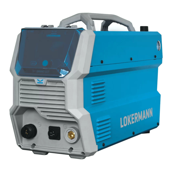
GRAND CUT 105 CNC
AIR PLASMA CUTTER
IMPORTANT: Read this Owner's Manual Completely before attempting to use this
equipment. Save this manual and keep it handy for quick reference. Pay particular
attention to the safety instructions we have provided for your protection. Contact your
distributor if you do not fully understand this manual.
Advertisement
Table of Contents

Related Manuals for LOKERMANN GRAND CUT 105 CNC


Summary of Contents for LOKERMANN GRAND CUT 105 CNC
- Page 1 THANK YOU FOR USING OUR PRODUCTS OPERATORS’ MANUAL GRAND CUT 105 CNC AIR PLASMA CUTTER IMPORTANT: Read this Owner’s Manual Completely before attempting to use this equipment. Save this manual and keep it handy for quick reference. Pay particular attention to the safety instructions we have provided for your protection. Contact your...
-
Page 2: Table Of Contents
CONTENT CONTENT §1 Safety §2 Overview §2.1 Features §2.2 Working Principle §2.3 Technical Data §2.4 Duty Cycle and Over-heat §3 Panel Functions & Descriptions §3.1 Front and rear panel layout of cutting machine §3.2 Control panel of cutting machine §3.2.1 Panel introduction §3.2.2 Display introduction §3.2.3 Language selection interface §4 Installation... -
Page 3: Safety
SAFETY §1 Safety Notice: The instructions are for reference only. The manufacturer reserves the right to explain the differences between the description and the product due to product changes and upgrades! Important Safety Precautions: Operation and maintenance of plasma ARC equipment can be dangerous to your health. - Page 4 SAFETY Antimony Chromium Mercury Beryllium Arsenic Cobalt Nickel Lead Barium Copper Selenium Silver Cadmium Manganese Vanadium Always read the Material Safety Data Sheets (MSDS) that should be supplied with the material you are using. These MSDSs will give you the information regarding the kind and amount of fumes and gases that may be dangerous to your health.
- Page 5 SAFETY material that cannot be removed must be protected. Ventilate all flammable or explosive vapors from the workplace. Do not cut or weld on containers that may have held combustibles. Provide a fire watch when working in an area where fire hazards may exist. ...
- Page 6 SAFETY shields.
-
Page 7: Overview
OVERVIEW §2 Overview §2.1 Features 1. New panel design: More trendy humanized. 2. LCD screen accurate setting & feedback of cutting output. 3. With CNC interface, it can synchronize with CNC machine tools. 4. IGBT parallel balanced current technology and digital control technology. 5. -
Page 8: Technical Data
OVERVIEW current parameter can be adjusted continuously and steplessly to meet with the requirements of cutting craft. §2.3 Technical Data Models GRAND CUT 105 CNC Parameters Rated input voltage (V) 3-400±10% Frequency (HZ) 50/60 Rated input current (A) 27.8 Rated input power (kVA) 19.3... -
Page 9: Duty Cycle And Over-Heat
The letter “X” stands for Duty Cycle, Relation of cutting current and which is defined as the portion of the duty cycle for GRAND CUT 105 CNC time a cutting machine can cut at maximum rated output current within a 10-minute cycle. -
Page 10: Panel Functions & Descriptions
PANEL FUNCTIONS & DESCRIPTIONS §3 Panel Functions & Descriptions §3.1 Front and rear panel layout of cutting machine 1. Plasma Torch Euro/ Central Connector. 2. CNC Interface Connection Port. 3. Earth Lead Connection Socket. 4. Compressed Air Inlet. 5. Power Switch: Turn on or off the power source. 6. -
Page 11: Control Panel Of Cutting Machine
PANEL FUNCTIONS & DESCRIPTIONS §3.2 Control panel of cutting machine §3.2.1 Panel introduction Cutting mode button: Press the button to select Standard cutting, Grid cutting and Gouging mode. Cutting current knob: counterclockwise rotation reduces the current and clockwise rotation increases the current. Screen: It displays cutting current, cutting mode and error codes. -
Page 12: Display Introduction
PANEL FUNCTIONS & DESCRIPTIONS §3.2.2 Display introduction 1. Current display: This is current display. Adjust it by the knob. Unit: A. the range of adjustment is 20~105A. 2. Cutting mode display: This will display the cutting mode currently in use. * 3. - Page 13 PANEL FUNCTIONS & DESCRIPTIONS Similar to the grid cutting mode, the difference is that the arc breaks immediately when the cutting torch nozzle leaves the workpiece surface. Grid Cutting As long as the cutting torch switch is pressed down, the arc will form. When the cutting torch leaves the workpiece surface, the arc will still exist.
-
Page 14: Language Selection Interface
PANEL FUNCTIONS & DESCRIPTIONS §3.2.3 Language selection interface Press the cutting mode button and hold it for 3s to enter the language selection interface. Here you can select the language through the knob. - Page 15 PANEL FUNCTIONS & DESCRIPTIONS...
-
Page 16: Installation
INSTALLATION §4 Installation §4.1 Unpacking Use the packing lists to identify and account for each item. 1. Inspect each item for possible shipping damage. If damage is evident, contact your distributor and/or shipping company before proceeding with the installation. 2. When using forklift, its arm length must be long enough to reach the outside so as to ensure lifting safely. -
Page 17: Gas Connections
INSTALLATION Induce the machines using power supply in the same time; Set the voltage stabilization device in the front of power cable input. §4.3 Gas Connections 1. Connecting Gas Supply to Unit Connect the gas line to the inlet port of the gas filter on the rear panel. 2. -
Page 18: Operation
OPERATION §5 Operation §5.1 Cutting Preparation 1) Tightly connect the power cable to electrical socket outlet (the input voltage, refer to the section 2 technology parameters). 2) To connect the gas line to the air supply equipment, the earth cable to the workpiece. - Page 19 OPERATION After Initialization Automatic Automatic Turn on Pre-gas press on the torch examine gas test for the power for 1s trigger for 5s source If the tip of touch, Shift to the The current the workpiece and workpiece, the will down to Ignite the the current higher pilot arc change...
- Page 20 OPERATION Account for the alarm indicator: 1) When the machine appears over-heat, the screen will display error code “E01 Overheat”. Over-heat: The alarm will release after the period of fan cooling. You can restart the machine. 2) When the air pressure is too lower, the screen will display error code “E12 Lack of gas”.
-
Page 21: About The Cut Voltage Divider
OPERATION §5.3 About the CUT voltage divider The CUT power supplies are equipped with an optional, factory-installed, four-position voltage divider that is designed to be safely connected without tools. The built-in voltage divider provides a scaled down arc voltage of 20:1, 30:1, 40:1, and 50:1 (maximum output of 18 V). - Page 22 OPERATION 1. Turn OFF the power and disconnect the power cord. 2. Remove the machine interface receptacle’s cover from the rear of the power supply. 3. Connect the machine interface cable to the power supply. Refer to the following table when connecting the CUT system to a torch height controller or CNC controller with a machine interface cable.
-
Page 23: Operation Environment
OPERATION Note: the table below for the shift and scale selection Scale selection 20:1 30:1 40:1 50:1 Dial number CNC control cable selectable type: Number Standard (m) 6.310.660 6.310.660-D 6.310660-E §5.4 Operation Environment ▲ Height above sea level ≤1000 M. ▲... -
Page 24: Operation Notices
OPERATION ▲ Protect the machine against high moisture, water and against direct sunshine. ▲ Take care that there is sufficient ventilation during welding. There must be at least 1- 1/2” (38cm) free distance between the machine and wall. §5.5 Operation Notices ▲... -
Page 25: Basic Trouble Shooting
BASIC TROUBLE SHOOTING §6 Basic Trouble Shooting §6.1 Basic Troubleshooting Guide WARNING There are extremely dangerous voltage and power levels present inside this unit. Do not attempt to diagnose or repair unless you have had training in power electronics measurement and troubleshooting techniques. §6.1.1 Basic troubles A. -
Page 26: Pilot Arc Troubles
BASIC TROUBLE SHOOTING §6.1.2 Pilot arc troubles A. Torch failed to ignite the arc when torch is triggered. 1. The shield cup is unfitted installation. Turn off the power source, install and screw it properly, then turn on the power source. 2. -
Page 27: Cutting Troubles
BASIC TROUBLE SHOOTING cycle specifications. 2. Gas pressure too low, check source for at least 65 psi/4.5 bar; adjust as needed. 3. Torch consumables worn, check torch shield cup, tip, starter element, and electrode; replace as needed. 4. Faulty components in unit, return for repair or have qualified technician repair per Service Manual.
Need help?
Do you have a question about the GRAND CUT 105 CNC and is the answer not in the manual?
Questions and answers