Table of Contents
Advertisement
S e r v i c e L i t e r a t u r e
The KGB packaged gas units are available in standard
cooling efficiency (024, 030, 036, 048 060, 072, 074 and
090). Cooling capacities range from 2 to 7-1/2 tons (7 to
26kW).
KGB024, 030, 036, 048, 060, 072, 074 units are available
in 65,000 BTUH heat capacity /KGB036, 048, 060, 072,
074 and 090 units are available in 108,000 BTUH (105,000
BTUH in earlier built units ) heat capacity. KGB048, 060,
072, 074 and 090 units are available in 150,000 BTUH (44
kW) heat sizes. Two stage heat is available in units with
108,000 (105,000 in earlier built units) and 150,000 BTUH
capacities. Gas heat sections are designed with alumi-
nized steel tube heat exchangers.
Information contained in this manual is intended for use
by qualified service technicians only. All specifications are
subject to change. Procedures outlined in this manual are
presented as a recommendation only and do not super-
sede or replace local or state codes.
If the unit must be lifted for service, rig unit by attaching
four cables to the holes located in the unit base rail (two
holes at each corner). Refer to the installation instructions
for the proper rigging technique.
WARNING
Improper
installation,
service or maintenance can cause property damage,
personal injury or loss of life. Installation and service
must be performed by a qualified installer or service
agency.
WARNING
Electric shock hazard. Can cause injury
or death. Before attempting to perform
any service or maintenance, turn the
electrical power to unit OFF at disconnect
switch(es). Unit may have multiple power
supplies.
CAUTION
As with any mechanical equipment, contact with
sharp sheet metal edges can result in personal
injury. Take care while handling this equipment and
wear gloves and protective clothing.
UNIT INFORMATION
UNIT INFORMATION
KGB024 through 090
adjustment,
alteration,
100004
09/2022
To prevent serious injury or death:
1- Lock-out/tag-out before performing maintenance.
2- If system power is required (e.g., smoke detector
maintenance), disable power to blower, remove
fan belt where applicable, and ensure all
controllers and thermostats are set to the "OFF"
position before performing maintenance.
3- Always keep hands, hair, clothing, jewelry, tools,
etc., away from moving parts.
Options . . . . . . . . . . . . . . . . . . . . . . .Page 2
Specifications . . . . . . . . . . . . . . . . . .Page 6
Spec. Gas Heat / High Altitude . . . Page 13
Blower Data. . . . . . . . . . . . . . . . . . . Page 14
Electrical Data . . . . . . . . . . . . . . . . . Page 31
I Unit Components . . . . . . . . . . . . . Page 35
II Placement and Installation . . . . . Page 48
III Start Up Operation . . . . . . . . . . . Page 48
IV Charging . . . . . . . . . . . . . . . . . . . Page 50
V System Service Checks . . . . . . . Page 60
VI Maintenance . . . . . . . . . . . . . . . . Page 62
VII Accessories . . . . . . . . . . . . . . . . Page 63
VIII Diagrams . . . . . . . . . . . . . . . . . . Page 69
Page 1
KGB SERIES
2 to 7-1/2 ton
7 to 26 kW
WARNING
Table of Contents
Advertisement
Table of Contents

Related Manuals for ALLIED COMMERCIAL KGB Series


Summary of Contents for ALLIED COMMERCIAL KGB Series
-
Page 1: Table Of Contents
KGB SERIES UNIT INFORMATION UNIT INFORMATION 2 to 7-1/2 ton 7 to 26 kW 100004 S e r v i c e L i t e r a t u r e 09/2022 KGB024 through 090 The KGB packaged gas units are available in standard cooling efficiency (024, 030, 036, 048 060, 072, 074 and 090). -
Page 2: Options
O P T IONS / A C C ESSORIES Unit Model No. Item Catalog COOLING SYSTEM Condensate Drain Trap 22H54 Copper 76W27 Conventional Fin/Tube Condenser Coil (replaces Environ™ Coil System) Factory ¹ O 74W42 Drain Pan Overflow Switch Low Ambient Kit 14D89 Efficiency High... - Page 3 OPTIONS / AC C ESSORIES Unit Model No. Item Catalog BLOWER - SUPPLY AIR Motors Direct Drive (ECM) - 0.33 hp (208/230V-1ph) Factory Direct Drive (ECM) - 0.50 hp (208/230V-1ph) Factory Direct Drive (ECM) - 0.75 hp (208/230V-1ph) Factory Direct Drive (ECM) - 1.0 hp (208/230V-1ph) Factory Direct Drive (PSC) - 0.5 hp (208/230V-3ph, 460V-3ph, 575V-3ph) Factory...
- Page 4 OPTIONS / AC C ESSORIES Unit Model No. Item Catalog ECONOMIZER Standard Economizer (Sensible Control) (Not for Title 24) Standard Economizer 23T20 OX OX OX OX OX OX OX OX Factory Installed Economizer - Includes Barometric Relief Dampers, Combination Outdoor Air/Exhaust Hood and Harness Field Installed Economizer - Barometric Relief Dampers, Combination Outdoor Air/Exhaust Hood and Harness are not furnished and must be ordered separately (see below)
- Page 5 OPTIONS / AC C ESSORIES Unit Model No. Item Catalog INDOOR AIR QUALITY Air Filters Healthy Climate High MERV 8 (16 x 20 x 2) 54W20 ® Efficiency Air Filters 52W37 MERV 13 (16 x 20 x 2) Order 4 per unit MERV 16 (16 x 20 x 2) 22H13 MERV 8 (20 x 20 x 2)
-
Page 6: Specifications
SP EC IFIC ATIONS - D IRECT D RIVE BLOWER 2 TO N | 2 .5 TO N General Data Nominal Tonnage 2 Ton 2.5 Ton Model No. KGB024S4E KGB030S4E Efficiency Type Standard Standard Blower Type Multi-Speed Multi-Speed Direct Drive ECM Direct Drive ECM Cooling Gross Cooling Capacity - Btuh... - Page 7 SP EC IFIC ATIONS - D IRECT D RIVE BLOWER 3 TO N | 4 TO N General Data Nominal Tonnage 3 Ton 3 Ton 4 Ton 4 Ton Model No. KGB036S4E KGB036S4D KGB048S4E KGB048S4D Efficiency Type Standard Standard Standard Standard Blower Type Multi-Speed...
- Page 8 SPEC IFIC ATION S - DIRECT DRIVE BLOWER 5 TO N General Data Nominal Tonnage 5 Ton 5 Ton Model No. KGB060S4E KGB060S4D Efficiency Type Standard Standard Blower Type Multi-Speed Multi-Speed Direct Direct Drive ECM Drive PSC Cooling Gross Cooling Capacity - Btuh 60,900 60,900 Performance...
- Page 9 S PEC IF ICATIONS - BELT DRIVE BLOWER S IN GLE S P EED - 3 TO N | 4 TO N | 5 TO N General Data Nominal Tonnage 3 Ton 4 Ton 5 Ton Model No. KGB036S4B KGB048S4B KGB060S4B Efficiency Type Standard...
- Page 10 SP EC IFIC ATIONS - BELT D RIVE BLOWER S ING LE S PEED - 6 TO N General Data Nominal Tonnage 6 Ton 6 Ton Model No. KGB072H4B KGB074S4B Efficiency Type High Standard Blower Type Single Speed Belt Drive Single Speed Belt Drive Cooling Gross Cooling Capacity - Btuh...
- Page 11 SP EC IFIC ATIONS - BELT D RIVE BLOWER T WO - SP EED - 6 TO N General Data Nominal Tonnage 6 Ton 6 Ton Model No. KGB074S4T KGB074H4T Efficiency Type Standard High Blower Type Two Speed Belt Drive Two Speed Belt Drive Cooling Gross Cooling Capacity - Btuh...
- Page 12 SP EC IFIC ATIONS - BELT D RIVE BLOWER SIN GLE AND T WO - SP EED - 7 . 5 TO N General Data Nominal Tonnage 7.5 Ton 7.5 Ton Model No. KGB090S4B KGB090S4T Efficiency Type Standard Standard Blower Type Single Speed Belt Drive Two Speed Belt Drive Cooling...
-
Page 13: Spec. Gas Heat / High Altitude
S PECIF ICATIONS - STAND ARD G AS HEAT TH R EE P H ASE M O DELS Model No. 072H 072H 072H 072H 072H 074H 074H 074H 074H 074H 090S 090S 074S 090S 074S 090S 074S 074S 074S Heat Input Type Standard Medium Medium... -
Page 14: Blower Data
BLO WER DATA D IR ECT D R IVE ECM - 2 TO N | 2.5 TO N KGB024S4E | KGB030S4E BLOWER TABLE INCLUDES RESISTANCE FOR BASE UNIT ONLY WITH DRY INDOOR COIL AND AIR FILTERS IN PLACE. FOR ALL UNITS ADD: 1 - Any factory installed options air resistance (heat section, economizer, etc.). - Page 15 BLO WER DATA DIR ECT D RIVE ECM - 3 TO N KGB036S4E BLOWER TABLE INCLUDES RESISTANCE FOR BASE UNIT ONLY WITH DRY INDOOR COIL AND AIR FILTERS IN PLACE. FOR ALL UNITS ADD: 1 - Any factory installed options air resistance (heat section, economizer, etc.). 2 - Any field installed accessories air resistance (duct resistance, diffuser, etc.).
- Page 16 BLO WER DATA D IRECT DR IVE ECM - 4 TO N KGB048S4E BLOWER TABLE INCLUDES RESISTANCE FOR BASE UNIT ONLY WITH DRY INDOOR COIL AND AIR FILTERS IN PLACE. FOR ALL UNITS ADD: 1 - Any factory installed options air resistance (larger gas heat section, economizer, wet coil, etc.) See page 46. 2 - Any field installed accessories air resistance (duct resistance, diffuser, etc.) See page 46.
- Page 17 BLO WER DATA D IRECT DR IVE ECM - 5 TO N KGB060S4E BLOWER TABLE INCLUDES RESISTANCE FOR BASE UNIT ONLY WITH DRY INDOOR COIL AND AIR FILTERS IN PLACE. FOR ALL UNITS ADD: 1 - Any factory installed options air resistance (larger gas heat section, economizer, wet coil, etc.) See page 46. 2 - Any field installed accessories air resistance (duct resistance, diffuser, etc.) See page 46.
- Page 18 BLOWER DATA D IR ECT D R IVE P SC - 3 TO N | 4 TO N KGB036S4D | KGB048S4D BLOWER TABLE INCLUDES RESISTANCE FOR BASE UNIT ONLY WITH DRY INDOOR COIL AND AIR FILTERS IN PLACE. FOR ALL UNITS ADD: 1 - Any factory installed options air resistance (larger gas heat section, economizer, wet coil, etc.) See page 46.
- Page 19 BLOWER D ATA D IR ECT D R IVE P S C - 5 TO N KGB060S4D BLOWER TABLE INCLUDES RESISTANCE FOR BASE UNIT ONLY WITH DRY INDOOR COIL AND AIR FILTERS IN PLACE. FOR ALL UNITS ADD: 1 - Any factory installed options air resistance (larger gas heat section, economizer, wet coil, etc.) See page 46. 2 - Any field installed accessories air resistance (duct resistance, diffuser, etc.) See page 46.
- Page 20 BLOWER B ELT D R IVE (S IN GLE S P EED ) - 3 TO N KGB036S4B BLOWER TABLE INCLUDES RESISTANCE FOR BASE UNIT ONLY WITH DRY INDOOR COIL AND AIR FILTERS IN PLACE. FOR ALL UNITS ADD: 1 - Any factory installed options air resistance (heat section, economizer, wet coil, etc.). 2 - Any field installed accessories air resistance (duct resistance, diffuser, etc.).
- Page 21 BLOWER DATA B ELT D R IVE (S IN GLE S P EED ) - 4 TO N KGB048S4B BLOWER TABLE INCLUDES RESISTANCE FOR BASE UNIT ONLY WITH DRY INDOOR COIL AND AIR FILTERS IN PLACE. FOR ALL UNITS ADD: 1 - Any factory installed options air resistance (heat section, economizer, wet coil, etc.).
- Page 22 BLOWER DATA B ELT D R IVE (S IN GLE S P EED ) - 5 TO N KGB060S4B BLOWER TABLE INCLUDES RESISTANCE FOR BASE UNIT ONLY WITH DRY INDOOR COIL AND AIR FILTERS IN PLACE. FOR ALL UNITS ADD: 1 - Any factory installed options air resistance (heat section, economizer, wet coil, etc.).
- Page 23 BLOWER DATA BELT D RIVE ( S IN GLE AND T WO - SP EED - 6 TO N (D O WN F LO W ) KGB074S4B | KGB074S4T BLOWER TABLE INCLUDES RESISTANCE FOR BASE UNIT ONLY WITH DRY INDOOR COIL AND AIR FILTERS IN PLACE. FOR ALL UNITS ADD: 1 - Any factory installed options air resistance (heat section, economizer, wet coil, etc.).
- Page 24 BLOWER DATA BELT D RIVE ( SIN GLE AND T WO - SP EED ) - 6 TO N (HO R IZO NTA L) KGB074S4B | KGB074S4T BLOWER TABLE INCLUDES RESISTANCE FOR BASE UNIT ONLY WITH DRY INDOOR COIL AND AIR FILTERS IN PLACE. FOR ALL UNITS ADD: 1 - Any factory installed options air resistance (heat section, economizer, wet coil, etc.).
- Page 25 BLO WER DATA BELT D RIVE ( S IN GLE AND T WO - SP EED ) - 6 TO N (D O WNF LO W ) KGB072H4B | KGB074H4T BLOWER TABLE INCLUDES RESISTANCE FOR BASE UNIT ONLY WITH DRY INDOOR COIL AND AIR FILTERS IN PLACE. FOR ALL UNITS ADD: 1 - Any factory installed options air resistance (heat section, economizer, etc.).
- Page 26 BLO WER DATA BELT D R IVE ( SING LE AN D T WO - S PEED ) - 6 TO N ( HO R IZO NTA L) KGB072H4B | KGB074H4T BLOWER TABLE INCLUDES RESISTANCE FOR BASE UNIT ONLY WITH DRY INDOOR COIL AND AIR FILTERS IN PLACE. FOR ALL UNITS ADD: 1 - Any factory installed options air resistance (heat section, economizer, etc.).
- Page 27 BLOWER DATA BELT D RIVE ( SING LE AND T WO - SP EED ) - 7 . 5 TO N (D O WNF LO W ) KGB090S4B | KGB090S4T BLOWER TABLE INCLUDES RESISTANCE FOR BASE UNIT ONLY WITH DRY INDOOR COIL AND AIR FILTERS IN PLACE. FOR ALL UNITS ADD: 1 - Any factory installed options air resistance (heat section, economizer, etc.).
- Page 28 BLOWER DATA BELT D RIVE ( SINGLE AN D T WO - S PEED ) - 7. 5 TO N (HO R IZO NTA L) KGB090S4B | KGB090S4T BLOWER TABLE INCLUDES RESISTANCE FOR BASE UNIT ONLY WITH DRY INDOOR COIL AND AIR FILTERS IN PLACE. FOR ALL UNITS ADD: 1 - Any factory installed options air resistance (heat section, economizer, etc.).
- Page 29 BLO WER DATA BELT DRIVE KIT SPECIFICATIONS - 036-074S Model Motor HP No. of Drive Kits and RPM Range Speeds Nominal Maximum 1.15 673-1010 - - - - - - - - - 897-1346 - - - - - - - - - 673-1010 - - -...
- Page 30 BLO WER DATA CEILING DIFFUSERS AIR RESISTANCE (in. w.g.) RTD9-65S Step–Down Diffuser RTD11-95S Step–Down Diffuser FD9-65S FD11-95S Air Volume Flush Flush 2 Ends 1 Side & All Ends & 2 Ends 1 Side & All Ends & Diffuser Diffuser Open 2 Ends Open Sides Open Open...
-
Page 31: Electrical Data
ELECTR ICAL D ATA DIR ECT D RIVE ECM - 2 TO N | 2.5 TO N ECM Model No. KGB024S4E KGB030S4E Voltage - 60hz 208/230V - 1 Ph 208/230V - 1 Ph Compressor Rated Load Amps 10.9 13.5 Locked Rotor Amps Outdoor Fan Full Load Amps Motor... - Page 32 ELECTR ICA L DATA D IRECT DR IVE P SC - 3 TO N Model No. KGB036S4D 208/230V - 3 Ph 460V - 3 Ph 575V - 3 Ph Voltage - 60hz Compressor Rated Load Amps Locked Rotor Amps Outdoor Fan Full Load Amps Motor Power Exhaust...
- Page 33 ELECTR ICAL D ATA D IR ECT D R IVE P S C - 5 TO N Model No. KGB060S4D 208/230V - 3 Ph 460V - 3 Ph 575V - 3 Ph Voltage - 60hz Compressor Rated Load Amps Locked Rotor Amps 38.9 Outdoor Fan Full Load Amps...
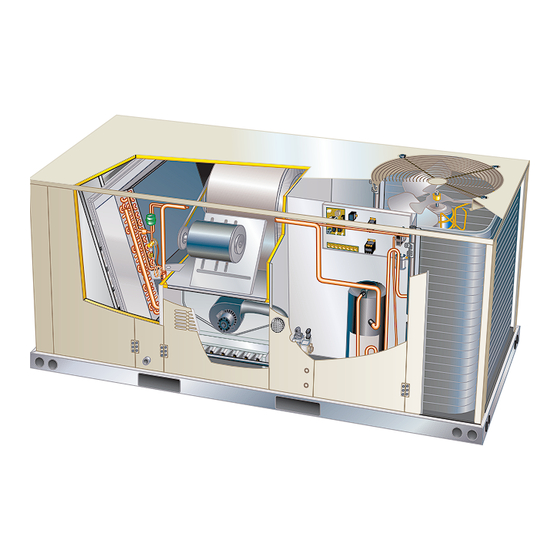
- Page 34 PARTS ARRANGEMENT FILTERS (4) BLOWER EVAPORATOR 024, 030, 036, 048 16 X 20 X 2” REFRIGERANT MOTOR COIL 060, 072, 090: 20 X 20 X 2” METERING DEVICE TB1 LOW VOLTAGE CONDENSER TERMINAL BLOCK ECONOMIZER (OPTIONAL) BLOWER CONDENSER COIL CONDENSATE DRAIN COMBUSTION BURNERS...
-
Page 35: I Unit Components
I-UNIT COMPONENTS 5-Fan Capacitor C1 (three phase) All 2 through 7-1/2 ton (7 through 21 kW) units are built to Fan capacitors C1 is used to assist in the start up of con- order units (BTO). The KGB unit components are shown denser fan B4. - Page 36 15-Gas Relay K72 (two stage units) TABLE 1 Relay K72 is normally closed and controls combustion air STATUS inducer B6. K72 switches the inducer B6 to high speed in Slow Flash Normal operation. No call for heat wwwresponse to two stage heat demand. Fast Flash Normal operation.
- Page 37 The control then proceeds to “steady state” mode where In all units each compressor is protected by a freezestat (S49) on the evaporator coil and a high pressure switch all inputs are monitored to ensure the limit switch, rollout (S4) on the discharge line. See figure 5. A Low ambient switch and prove switch are closed as well as flame is switch (S11) is available as a field accessory for additional present.
- Page 38 PLUMBING and S49 FREEZESTAT LOCATION DRIER CONTROL AND CONDENSER COIL EVAPORATOR COMPONENTS COIL SECTION REFRIGERANT METERING DEVICE RETURN AIR INDOOR BLOWER SECTION SECTION PROCESS TUBE (used for charging) HEAT SECTION COMPRESSOR 060, 090 024S, 030S, 036S, 048S 072/074 FIGURE 5 Page 38...
- Page 39 2-Freezestat S49 C-Blower Compartment Each unit is equipped with a low temperature switch (freez- 1-Blower Wheels estat) located on a return bend of each evaporator coil. All belt drive units use 10” x 10” (254 mm x 254 mm) blow The freezestat is wired in series with the compressor con- er wheels.
- Page 40 B-Determining Unit CFM - Single-Speed, Direct Drive Blowers BLOWER SPEED FACTORY SETTINGS 024, 030, & 1 - The following measurements must be made with air 048 Units 036 Units 060 Units filters in place. 2 - With all access panels in place, measure static pressure external to unit (from supply to return).
- Page 41 FIELD-ADJUSTABLE BLOWER SPEEDS - DIRECT DRIVE 208/230V HIGH SPEED - ALL UNITS LOW SPEED 024, 030, 036, 048, UNITS L1-Terminal COM L2-Terminal HIGH L1-Terminal COM TERMINAL 1 L2-Terminal LOW REMAINS AT COMMON 1-COM 2-HI 3-MED 4-LOW MEDIUM SPEED 1-COM 024, 030, 036, 048 UNITS 2-HI L1-Terminal COM 3-MED...
- Page 42 C-Determining Unit CFM - Multi-Stage, Direct Drive TABLE 4 Blowers TWO-SPEED BLOWER OPERATION 1 - Refer to multi-stage direct drive blower tables, KGB074, 090S4T UNITS the measured static pressure, and the factory-set Thermostat Blower Speed blower speed to determine CFM. G (P350/J350)* 2 - If CFM is lower than the design specified CFM, G (P350/J351)
- Page 43 BLOWER ASSEMBLY TO INCREASE CFM TO DECREASE CFM LOOSEN ALLEN SCREW & TURN PULLEY TURN PULLEY CLOCKWISE COUNTERCLOCKWISE SIDE VIEW LOOSEN ALLEN SCREW TO ADJUST CFM MOTOR ALLEN SCREW PULLEY TO INCREASE BELT TENSION 1-Loosen four bolts securing motor base to mounting frame.
- Page 44 INSTALL BELT ADJUST BELT TENSIONER INDICATOR SHOULD BE DRIVER MAXIMUM BETWEEN MINIMUM AND TENSIONER PULLEY TENSION MAXIMUM TENSION LINES MINIMUM TENSION TIGHTEN MOUNTING BOLT TO 22 LB./FT. USING 9/16” WRENCH DRIVEN PULLEY BRACKET TIGHTEST BELT TENSIONER ROTATE DRIVEN POSITION PULLEY TO SEAT BELT TIGHTER FACTORY-SET BELT POSITION...
- Page 45 TABLE 6 DRIVE COMPONENT MANUFACTURER’S NUMBERS DRIVE COMPONENTS Drive No. Motor Pulley Blower Pulley Belts Browning No. OEM Part No. Browning No. OEM Part No. Browning No. OEM Part No. 1VP34 X 7/8 31K6901 AK54 X 1 100244-19 100245-17 1VP34 X 7/8 31K6901 AK49 X 1 100244-18...
- Page 46 D-GAS HEAT COMPONENTS 2-Burner Box Assembly (Figure 17) KGB024, 030, 036, 048, 060, 072, 074S units are avail- The burner assembly consists of a spark electrode, flame able in 65,000 BTUH (19 kW) heat capacity. KG036, 048, sensing electrode and gas valve. Ignition board A3 con- 060, 072 074H and 090 units are available in 108,000 trols all functions of the assembly.
- Page 47 3-Primary High Temperature Limit S10 On two stage natural gas units the inducer will operate on low speed for first stage heat (W1) and ramp up to high S10 is a SPST N.C. high temperature primary limit for gas speed for second stage heat (W2). heat in KGB024-090 units.
-
Page 48: Placement And Installation
III-START UP - OPERATION IGNITOR A-Preliminary and Seasonal Checks SPARK GAP SHOULD BE 1/8” 1 - Make sure the unit is installed in accordance with (3mm) the installation instructions and applicable codes. 2 - Inspect all electrical wiring, both field and factory installed for loose connections. - Page 49 WARNING HONEYWELL VR8215S GAS VALVE MANIFOLD Single-Stage SMOKE POTENTIAL MANIFOLD PRESSURE PRESSURE The heat exchanger in this unit could be a source OUTLET ADJUSTMENT of smoke on initial firing. Take precautions with SCREW respect to building occupants and property. Vent initial supply air outside when possible.
-
Page 50: Charging
C-Cooling Start up IV-CHARGING Operation A-Refrigerant Charge and Check - All-Aluminum Coil WARNING-Do not exceed nameplate charge under 1 - Initiate first and second stage cooling demands any condition. according to instructions provided with thermostat. This unit is factory charged and should require no further 2 - KGB024/090 No Economizer Installed in Unit adjustment. - Page 51 TABLE 7 508708-02 KGB/KCB024 Normal Operating Pressures Outdoor Coil Entering Air Tempoerature Suct Disc Suct Disc Suct Disc Suct Disc Suct Disc Suct Disc (psig) (psig) (psig) (psig) (psig) (psig) (psig) (psig) (psig) (psig) (psig) (psig) KGB/KCB 024 Charging Curves 580708-02 Outdoor Temperature (°F) 115°...
- Page 52 TABLE 8 508709-02 KGB/KCB030 Normal Operating Pressures Outdoor Coil Entering Air Tempoerature Suct Disc Suct Disc Suct Disc Suct Disc Suct Disc Suct Disc (psig) (psig) (psig) (psig) (psig) (psig) (psig) (psig) (psig) (psig) (psig) (psig) KGB/KCB 030 Charging Curves 580709-02 Outdoor Temperature (°F) 115°...
- Page 53 TABLE 9 508710-02 KGB/KCB036 Normal Operating Pressures Outdoor Coil Entering Air Tempoerature Suct Disc Suct Disc Suct Disc Suct Disc Suct Disc Suct Disc (psig) (psig) (psig) (psig) (psig) (psig) (psig) (psig) (psig) (psig) (psig) (psig) 1376 KGB/KCB 036 Charging Curves 580710-02 Outdoor Temperature (°F) 115°...
- Page 54 TABLE 10 508711-02 KGB/KCB048 Normal Operating Pressures Outdoor Coil Entering Air Tempoerature Suct Disc Suct Disc Suct Disc Suct Disc Suct Disc Suct Disc (psig) (psig) (psig) (psig) (psig) (psig) (psig) (psig) (psig) (psig) (psig) (psig) KGB/KCB 048 Charging Curves 580711-02 Outdoor Temperature (°F) 115°...
- Page 55 TABLE 11 508712-02 KGB/KCB 060 Normal Operating Pressures Outdoor Coil Entering Air Tempoerature Suct Disc Suct Disc Suct Disc Suct Disc Suct Disc Suct Disc (psig) (psig) (psig) (psig) (psig) (psig) (psig) (psig) (psig) (psig) (psig) (psig) KGB/KCB 060 Charging Curves 580712-02 Outdoor Temperature (°F) 115°...
- Page 56 TABLE 12 508996-01 KGB/KCB 072H Normal Operating Pressures Outdoor Coil Entering Air Tempoerature Suct Disc Suct Disc Suct Disc Suct Disc Suct Disc Suct Disc (psig) (psig) (psig) (psig) (psig) (psig) (psig) (psig) (psig) (psig) (psig) (psig) 580996-01 KGB/KCB 072 Charging Curves Outdoor Temperature (°F) 115°...
- Page 57 TABLE 13 508791-01 KGB/KCB 074S & H Normal Operating Pressures Outdoor Coil Entering Air Tempoerature Suct Disc Suct Disc Suct Disc Suct Disc Suct Disc Suct Disc (psig) (psig) (psig) (psig) (psig) (psig) (psig) (psig) (psig) (psig) (psig) (psig) KGB/KCB074S & H Charging Curves 580791-01 Outdoor Temperature (°F) 115°...
- Page 58 TABLE 14 508544-02 KGB/KCB 090 Normal Operating Pressures Outdoor Coil Entering Air Tempoerature Suct Disc Suct Disc Suct Disc Suct Disc Suct Disc Suct Disc (psig) (psig) (psig) (psig) (psig) (psig) (psig) (psig) (psig) (psig) (psig) (psig) KGB/KCB 090 Charging Curves 580544-02 Outdoor Temperature (°F) 115°...
- Page 59 B-Refrigerant Charge and Check - Fin/Tube Coil TABLE 16 KG/KC 024S, 030S, 036S, 048S, 060S, 074S, 090S KGB/KCB030S Fin/Tube - W & W/O Reheat Outdoor Coil WARNING-Do not exceed nameplate charge under DIscharge any condition. Entering Air Suction 5 psig 10psig Temp This unit is factory charged and should require no further...
-
Page 60: System Service Checks
2 - Use the liquid line pressure and a PT chart to TABLE 20 determine the saturated liquid temperature. KGB/KCB074S Fin/Tube - W & W/O Reheat 3 - Measure the liquid line temperature at the condenser Outdoor Coil outlet. DIscharge Entering Air Suction 5 psig... - Page 61 When checking piping connection for gas leaks, use the 3 - After allowing the unit to stabilize for five minutes, preferred means. Common kitchen detergents can cause record the manifold pressure and compare to the harmful corrosion on various metals used in gas piping. values below.
-
Page 62: Maintenance
The electrodes should be located so the tips are at least A-Filters 1/2” (12.7 mm) inside the flame envelope. Do not bend Units are equipped with temporary filters which must be electrodes. To measure flame current, follow the proce- replaced prior to building occupation. See table 25 for dure on the following page: correct filter size. -
Page 63: Accessories
D-Combustion Air Inducer H-Condenser Coil A combustion air proving switch checks combustion air All-Aluminum Environ Coils inducer operation before allowing power to the gas con- Clean condenser coil annually with water and inspect troller. monthly during the cooling season. Gas controller will not operate if inducer is obstructed. Un- Clean the all-aluminum coil by spraying the coil steadily der normal operating conditions, the combustion air induc- and uniformly from top to bottom. - Page 64 OUTDOOR AIR DAMPER ASSEMBLED ROOF MOUNTING FRAME MOTORIZED SEMBLY FIGURE 24 TYPICAL FLASHING DETAIL DAMPER UNIT BASE MOTOR BOTTOM UNIT BASE RAIL MANUAL OUTDOOR AIR FIBERGLASS DAMPER - PAINTED SIDE INSULATION (Furnished) FIGURE 26 COUNTER FLASHING D-Supply and Return Diffusers (all units) (Field Supplied) NAILER STRIP (Furnished)
- Page 65 ECONOMIZER CONTROLS A6 ENTHALPY CONTROLLER ENTHALPY SENSOR (OTHER SIDE OF PANEL) MUM POSITION ENTHALPY CONTROL IAQ MAXIMUM POSITION Open (set higher than minimum position) DAMPER IAQ READING IS MOTOR ABOVE SETPOINT MIXED AIR SENSOR (R1) AND WIRING IN IAQ SETPOINT POWER EXHAUST WIRES THIS BUNDLE Free...
- Page 66 Damper Minimum Position 8 - Draw a horizontal line where the two lines meet. Read the percent of fresh air intake on the side. NOTE - A jumper is factory-installed between TB1 R and 9 - If fresh air percentage is less than desired, adjust OC terminals to maintain occupied status (allowing min- MIN POS SET potentiometer higher.
- Page 67 Economizer Operation Set damper minimum position in the same manner as economizer minimum position. Adjust motorized damper The occupied time period is determined by the thermostat position using the thumbwheel on the damper motor. See or energy management system. figure 29. Manual damper fresh air intake percentage can Outdoor Air Not Suitable: be determined in the same manner.
- Page 68 Three different types of control systems may be used with POWER EXHAUST FAN the KGB series units. All thermostat wiring is connected to TB1 located in the control box. Each thermostat has addi- tional control options available. See thermostat installation instructions for more detail.
-
Page 69: Diagrams
VIII-Wiring Diagrams and Sequence of Operation KGB024/060 P VOLTAGE UNIT DIAGRAM Page 69... - Page 70 KGB036/090 G, J, M &Y VOLTAGE UNIT DIAGRAM Page 70...
- Page 71 KGB024/090 P, Y, G, J & M Voltage Sequence of Operation Power: 1 - Line voltage from unit disconnect energizes transformer T1. T1 provides 24VAC power to terminal strip TB1. TB1 provides 24VAC to the unit cooling, heating and blower controls. Blower Operation: 2 - Indoor thermostat terminal G energizes blower contactor K3 with 24VAC.
- Page 72 KGB-074 Two-Stage Units 1. First-stage cooling demand Y1 2. Relay K239 directs voltage through relay K250 to energize contactor K3. 3. Blower contactor K3 energizes blower B3 on low speed. 4. Second-stage cooling demand Y2 gizes tor K37 5. Contactor K37 energizes blower B3 on high speed.
- Page 73 GAS HEAT FOR KGB024/090 UNITS End of Second Stage Heat: First Stage Heat: 10. Heating demand is satisfied. Terminal W2 (second The thermostat initiates W1 heating demand. stage) is de-energized. 24VAC is 11. Second stage heat is de-energized on GV1 by ignition mary limit S10 and N.C.
- Page 74 ELECTRONIC OR ELECTROMECHANICAL THERMOSTAT POWER: Terminal strip TB1 found in the main control box supplies thermostat components with 24VAC. OPERATION: TB1 receives data from the electronic thermostat A2 (Y1, Y2, W1, W2, G) and energizes the appropriate components for heat or cool demand. Page 74...
- Page 75 ECONOMIZER SEQUENCE OF OPERATION POWER: Terminal strip TB1 found in the main control panel energizes the economizer components with 24VAC. OPERATION: Enthalpy trol module A6 when to power the damper motor B7. Economizer control module A6 supplies B7 with 0 - 10 VDC to control the positioning of economizer. The dam er actuator rovides 2 to 10 VDC osition feedback.
- Page 76 OUTDOOR AIR DAMPER SEQUENCE OF OPERATION OPERATION: Occupied Mode tion. Unoccupied Mode Dampers remain closed. Page 76...
Need help?
Do you have a question about the KGB Series and is the answer not in the manual?
Questions and answers