Table of Contents
Advertisement
Litho U.S.A.
©2006
WARNING
Improper installation, adjustment, alteration, ser-
vice or maintenance can cause property damage,
personal injury or loss of life. Installation and ser-
vice must be performed by a qualified installer, ser-
vice agency or the gas supplier
Table Of Contents
. . . . . . . . . . . . . . . . . . . . . . . . . . . . . . . . . . . . . .
. . . . . . . . . . . . . . . . . . . . . . . . . . . . . . .
. . . . . . . . . . . . . . . . . . . . . . . . . . . . . . . . . . . . . . . . . .
. . . . . . . . . . . . . . . . . . . . . . . . . . . . . . . . . . . . .
. . . . . . . . . . . . . . . . . . . . . . . . . . . . . . . . . . . . . .
. . . . . . . . . . . . . . . . . . . . . . . . . . . . . . . . . .
. . . . . . . . . . . . . . . . . . . . . . . . . . . . .
. . . . . . . . . . . . . . . . . . . . . . . . . . . . . . . .
. . . . . . . . . . . . . . . . . . . . . . . . . . . . . . . . . . . . . . .
. . . . . . . . . . . . . . . . . . . . . . . . . . .
. . . . . . . . . . . . . . . . . . . . . . . . . . . . . . .
RETAIN THESE INSTRUCTIONS FOR FUTURE REFERENCE
10/06
*2P1006*
. . . . . . . . . . . . . . . . . . . . . . . . . .
INSTALLATION
INSTRUCTIONS
TGA/TCA180
TGA/TCA210
TGA/TCA240
TGA/TCA300S
GAS AND COOLING PACKAGED UNITS
505,143M
1
10/2006
2
Supersedes 12/2005
3
3
3
. . . . . . . . . . . . . . . . . . . . . . . . . . . . . . . . . . . . . .
4
4
4
5
5
6
6
. . . . . . . . . . . . . . . . . . . . . . . . . . . . . . . . . . . . . . . . . .
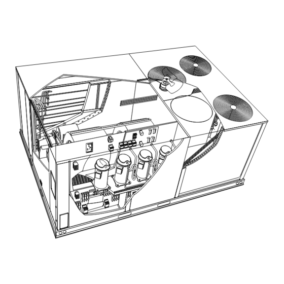
TCA240H SHOWN
(15 Ton)
(17.5 Ton)
(20 Ton)
(25 Ton)
. . . . . . . . . . . . . . . . . . . . . . . . . . . . .
. . . . . . . . . . . . . . . . . .
. . . . . . . . . . . . . . . . . . . . . . . . . . . . . . . . . .
. . . . . . . . . . . . . . . . . . . . . . . . . . . . . . . . .
. . . . . . . . . . . . . . . . . .
. . . . . . . . . . . . . . . . . . . . . . . . . . . . . .
505,143M
*P505143M*
6
7
8
14
17
18
19
19
Advertisement
Table of Contents

Related Manuals for ALLIED COMMERCIAL TGA180


Summary of Contents for ALLIED COMMERCIAL TGA180
-
Page 1: Table Of Contents
INSTALLATION Litho U.S.A. INSTRUCTIONS ©2006 WARNING TGA/TCA180 (15 Ton) Improper installation, adjustment, alteration, ser- TGA/TCA210 (17.5 Ton) vice or maintenance can cause property damage, personal injury or loss of life. Installation and ser- TGA/TCA240 (20 Ton) vice must be performed by a qualified installer, ser- vice agency or the gas supplier TGA/TCA300S (25 Ton) -
Page 2: Dimensions
TGA/TCA180, 210, 240, 300S DIMENSIONS − Electric heat section shown OUTDOOR Note: Optional equipment shown for infor- OPTIONAL OUTDOOR AIR HOOD COIL INTAKE mation only. Availability of units and options 4-1/4 varies by brand. (108) 12-3/8 60-1/2 (1537) OPTIONAL (314) 15 (381) ECONOMIZER DAMPER BOTTOM RETURN... -
Page 3: Parts Arrangements
TGA180, 210, 240, 300S PARTS ARRANGEMENT FILTERS INDOOR COIL (SIX − 24 X 24 X 2") ECONOMIZER DAMPERS OUTDOOR (OPTIONAL) FANS BLOWERS FILTER DRIERS BLOWER MOTOR OUTDOOR COIL CONDENSATE DRAIN COMPRESSORS − MCC (A45) 4TH COMPRESSOR CONTROL ON 210H, 240H, &... -
Page 4: Shipping And Packing List
Use of this unit as a construction heater or air conditioner CAUTION is not recommended during any phase of construction. Very low return air temperatures, harmful vapors and Danger of sharp metallic edges. Can cause injury. operation of the unit with clogged or misplaced filters will Take care when servicing unit to avoid accidental contact with sharp edges. -
Page 5: Unit Support
B−Horizontal Discharge Applications Unit Support 1− Units installed in horizontal airflow applications must In downflow discharge installations, install the unit on a use an LARMF horizontal roof mounting frame. The non−combustible surface only. Unit may be installed on supply air duct connects to the LARMF horizontal combustible surfaces when used in horizontal discharge supply air opening. -
Page 6: Condensate Drains
RIGGING Connect Gas Piping (Gas Units) *WEIGHT UNIT Before connecting piping, check with gas company or CAUTION − Do not LBS. authorities having jurisdiction local code walk on unit. 2660 1207 requirements. When installing gas supply piping, length 2525 1145 of run from gas meter must be considered in determining *Maximum weight with all accessories. -
Page 7: Pressure Test Gas Piping
Pressure Test Gas Piping (Gas Units) High Altitude Derate Units may be installed at altitudes up to 2000 feet (610 m) When pressure testing gas lines, the gas valve must above sea level without any modification. At altitudes be disconnected and isolated. Gas valves can be above 2000 feet (610 m), units must be derated to match damaged if subjected to more than 0.5 psig (3.48kPa). -
Page 8: Unit Start−Up
B−Control Wiring 24 VOLT FIELD WIRING WITH ELECTRONIC AND 1− Route thermostat cable or wires from subbase to ELECTRO−MECHANICAL THERMOSTATS unit MCC (A45) board in control box (refer to unit A2 THERMOSTAT A45 MCC dimensions to locate bottom and side power entry CONTROL and parts arrangement for location of MCC board). -
Page 9: Blower Operation And Adjustments
B−MCC (A45) Control Board Blower Operation and Adjustments 1− Make sure there is no heating, cooling, or blower A−Three Phase Scroll Compressor Voltage Phasing demand from thermostat. Apply power to unit. Three phase scroll compressors must be phased 2− Locate green heartbeat LED on MCC board. See sequentially to ensure correct compressor and blower figure 7. - Page 10 BLOWER ASSEMBLY TO INCREASE CFM LOOSEN ALLEN SCREW & TO INCREASE BELT TENSION TURN PULLEY CLOCKWISE 1−Loosen four screws securing blower motor to TO DECREASE CFM sliding base. TURN PULLEY 2−Turn adjusting screw to the left, or counter- COUNTERCLOCKWISE clockwise, to move the motor downward and tighten the belt.
- Page 11 Example: Deflection distance of a 40" span would be PULLEY ALIGNMENT 40/64" or 5/8". Example: Deflection distance of a 400mm span ALIGNED would be 6mm. 3− Measure belt deflection force. For a used belt, the deflection force should be 5 lbs. (35kPa). A new belt deflection force should be 7 lbs.
- Page 12 TABLE 4 180, 210, 240, 300S BASE UNIT BLOWER PERFORMANCE BLOWER TABLE INCLUDES RESISTANCE FOR BASE UNIT ONLY WITH DRY INDOOR COIL & AIR FILTERS IN PLACE. FOR ALL UNITS ADD: 1 − Wet indoor coil air resistance of selected unit. 2 −...
- Page 13 TABLE 5 OPTION / ACCESSORY AIR RESISTANCE Total Resistance − inches water gauge (Pa) Air Volume Wet Indoor Gas Heat Exchanger LARMFH30/36 LARMFH18/24 Coil (TG Models) Horizontal Horizontal Electric Electric Horizontal Horizontal Econo- Roof 210H, Heat Roof mizer Mounting 210S 240H, Standard Medium...
- Page 14 TABLE 7 MANUFACTURER’S NUMBERS DRIVE COMPONENTS ADJUSTABLE SHEAVE FIXED SHEAVE BELTS SPLIT BUSHING OEM Part OEM Part Supplier OEM Part Supplier OEM Part Drive Supplier No. Supplier No. H.P. 1VP40x7/8 79J0301 BK95X1−7/16 80K1601 BX59 59A5001 1VP40x7/8 79J0301 BK72x1-7/16 100244−13 BX56 100245−11 1VP50x1−1/8 P−8−1977...
-
Page 15: Cooling Start−Up
Cooling Start−Up REFRIGERANT STAGES FOUR−COMPRESSOR UNITS The thermostat specified for use on this unit has three Circuit 1 = Stage 1 cooling outputs. Circuit 2 = Stage 2 Circuit 3 & 4 = Stage 3 A−Operation 1− Remove coil covers before starting unit. 2−... - Page 16 B−Refrigerant Charge and Check TABLE 9 TGA/TCA180H NORMAL OPERATING PRESSURES WARNING−Do not exceed nameplate charge under CIRCUIT 1 CIRCUIT 2 CIRCUIT 3 Outdoor Outdoor any condition. Coil Dis. Suc. Dis. Suc. Dis. Suc. This unit is factory charged and should require no further Entering Air Temp psig...
- Page 17 TABLE 13 3− Do not use the approach method if system pressures TCA/TGA240H NORMAL OPERATING PRESSURES do not match pressures in tables 8 through 14. The CIRCUIT CIRCUIT CIRCUIT CIRCUIT approach method is not valid for grossly over or Outdoor Outdoor C il Coil...
-
Page 18: Gas Heat Start−Up
This unit is equipped with an automatic spark ignition Gas Heat Start−Up (Gas Units) system. There is no pilot. In case of a safety shutdown, FOR YOUR SAFETY READ BEFORE LIGHTING move thermostat switch to OFF and return the thermostat switch to HEAT to reset ignition control. -
Page 19: Heating Operation And Adjustments
3− This appliance is equipped with an ignition device Heating Operation and Adjustments which automatically lights the burner. Do not try to (Gas Units) light the burner by hand. 4− Open or remove the heat section access panel. First Stage Heat: 5−... -
Page 20: Electric Heat Start−Up
B−Ignition Control Diagnostic LED’s Service TABLE 16 The unit should be inspected once a year by a qualified IGNITION CONTROL HEARTBEAT LED STATUS service technician. Indicates Flashes CAUTION Slow Normal operation. No call for heat. Label all wires prior to disconnection when servic- Fast Normal operation. - Page 21 B−Lubrication 4− Locate the ignitor under the left burners. Check ignitor spark gap with appropriately sized twist drills All motors are lubricated at the factory. No further or feeler gauges. See figure 19. lubrication is required. Blower shaft bearings are prelubricated. For extended IGNITOR bearing life, relubricate at least once every two years with SPARK GAP...
- Page 22 IGNITOR AND SENSOR POSITION IGNITOR SENSOR TOP VIEW SIDE VIEW IGNITOR SIDE VIEW SENSOR Gas Flow Gas Flow 1−3/4" 1−3/8" (45mm) (35mm) 13/16" 3/8" (21mm) (10mm) BURNER BOX FIGURE 20 Page 21...
- Page 23 D−Combustion Air Inducer (Gas Units) E−Flue Passageway and Flue Box (Gas Units) A combustion air proving switch checks combustion air 1− Remove combustion air inducer assembly as inducer operation before allowing power to the gas described in section D. controller. Gas controller will not operate if inducer is 2−...
- Page 24 CLEAN CONDENSER COIL CONDENSER ACCESS PANEL TOP VIEW 1− Remove unit top panel and both condenser access INDOOR COIL panels. 2− Remove screws securing coil end plates to mullions. BLOWER 3− Remove clips connecting coils slabs and separate slabs 3−4" (76−102mm). 4−...
Need help?
Do you have a question about the TGA180 and is the answer not in the manual?
Questions and answers