Table of Contents
Advertisement
Quick Links
E2019
WARNING
Improper installation, adjustment, alteration, ser
vice or maintenance can cause property damage,
personal injury or loss of life. Installation and ser
vice must be performed by a licensed professional
HVAC installer or equivalent, service agency, or the
gas supplier
CAUTION
As with any mechanical equipment, contact with
sharp sheet metal edges can result in personal in
jury. Take care while handling this equipment and
wear gloves and protective clothing.
Table of Contents
. . . . . . . . . . . . . . . . . . . . . . . . . . . . . . . . .
. . . . . . . . . . . . . . . . . . . . . . . . .
. . . . . . . . . . . . . . . . . . . .
. . . . . . . . . . . . . . . . . . . . . . . . . . . . . . . . . . . .
. . . . . . . . . . . . . . . . . . . . . . . . . . . . . . . .
. . . . . . . . . . . . . . . . . . . . . . . . . . . .
. . . . . . . . . . . . . . . . . . . . . . .
. . . . . . . . . . . . . . . . . . . . . . . . . .
. . . . . . . . . . . . . . . . . . . . . . . . . . . . . . . . .
. . . . . . . . . . . . . . . . . . . . .
. . . . . . . . . . . . . . . . . . . . . . . . .
. . . . . . . . . . . . . . . . . . . . . . .
RETAIN THESE INSTRUCTIONS FOR FUTURE REFERENCE
INSTALLATION
INSTRUCTIONS
LGH/LCH156H
LGH/LCH180H
LGH/LCH180U
LGH/LCH210H
LGH/LCH240H
LGH/LCH240U
LGH/LCH300S
ROOFTOP PACKAGED UNITS
507124-07
2/2019
Page 2
Supersedes 507124-06
Page 5
Page 6
Page 6
Page 7
Page 8
Page 8
Page 8
Page 9
Page 10
Page 10
. . . . . . . . . . . . . . . . . . . . . . . . . . . . . . . . . . . .
Page 10
(13 Ton)
(15 Ton)
(15 Ton)
(17.5 Ton)
(20 Ton)
(20 Ton)
(25 Ton)
. . . . . . . . . . . .
. . . . . . . . . . . . . . . . . . . . . . . . . . . .
. . . . . . . . . . . . . . . . . . . . . . . . . . .
. . . . . . . . . . . .
. . . . . . . . . . . . . . . . . . . . . . . .
. . . . . . . . . . . . . . . . . .
. . . . . . . . . . . . . .
. . . . . . . . . . . . .
. . . . . . . .
. . . . . . . . . . . . .
LCH180U SHOWN
Page 13
Page 20
Page 55
Page 57
Page 57
Page 58
Page 60
Page 63
Page 65
Page 69
Page 71
Advertisement
Table of Contents

Related Manuals for ALLIED COMMERCIAL LCH156H


Summary of Contents for ALLIED COMMERCIAL LCH156H
-
Page 1: Table Of Contents
E2019 INSTALLATION WARNING INSTRUCTIONS Improper installation, adjustment, alteration, ser LGH/LCH156H vice or maintenance can cause property damage, (13 Ton) personal injury or loss of life. Installation and ser vice must be performed by a licensed professional LGH/LCH180H (15 Ton) HVAC installer or equivalent, service agency, or the... -
Page 2: Dimensions
LGH/LCH156 Unit Dimensions - Inches (mm) - Gas Heat Section Shown 107−3/4(2737) BASE 4−1/4 (108) 12−3/8 60−1/2 (1537) (314) 15 (381) BOTTOM RETURN 28−3/8 AIR OPENING (721) BOTTOM SUPPL Y AIR OPENINGS 18 (457) 91−1/8 (2315) ALTERNATE (THRU THE BASE) BASE CONDENSATE DRAIN LOCATION 4−1/2... - Page 3 LGH/LCH180H Unit Dimensions - Inches (mm) - Gas Heat Section Shown 133−1/8 (3394) 4−1/4 (108) 12−3/8 60−1/2 (1537) (314) 15 (381) BOTTOM RETURN 28−3/8 AIR OPENING (721) 91−1/8 BOTTOM SUPPL Y (2315) AIR OPENINGS 18 (457) ALTERNATE (THRU THE BASE) CONDENSA TE DRAIN LOCATION 4−1/2 5−5/8 (143)
- Page 4 LGH/LCH180U, 210, 240H/U & 300S Unit Dimensions - Inches (mm) - Gas Heat Section Shown 133−1/8 (3381) 4−1/4 (108) 12−3/8 60−1/2 (1537) (314) 15 (381) BOTTOM RETURN 28−3/8 AIR OPENING (721) BOTTOM SUPPL Y 91−1/8 AIR OPENINGS (2315) 18 (457) ALTERNATE (THRU THE BASE) CONDENSA TE DRAIN LOCATION 4−1/2...
-
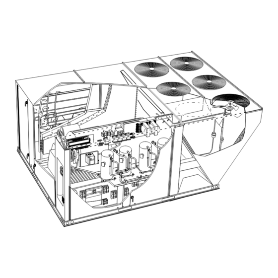
Page 5: Parts Arrangements
LGH156, 180H/U, 210, 240H/U, 300S PARTS ARRANGEMENT CONDENSER FANS 180H Shown (3 FANS ON 156 UNITS; 6 EVAPORATOR FANS ON 180U, 210, 240H/U, FILTERS ECONOMIZER COIL & 300S UNITS (SIX - 24 X 24 X 2”) DAMPERS (OPTIONAL) BLOWERS UNIT CONTROLLER INVERTER (OPTIONAL) -
Page 6: Shipping And Packing List
LGH unit except for the heating section. Optional electric Air Hood heat is factory- or field-installed in LCH units. LGH and LCH156H, 180H, 210H, 240H, & 300S units have identical refrigerant circuits with respective 13, 15, 17‐1/2, 20 and 25 ton cooling capacities. 156H, 180H and 210H units contain three compressors;... -
Page 7: Unit Support
Unit Support NOTICE In downflow discharge installations, install the unit on a Roof Damage! non-combustible surface only. Unit may be installed on This system contains both refrigerant and oil. combustible surfaces when used in horizontal discharge Some rubber roofing material may absorb oil, applications or in downflow discharge applications when causing the rubber to swell. -
Page 8: Duct Connection
B-Horizontal Discharge Applications RIGGING 1- Units installed in horizontal airflow applications must use an LARMFH18/24 horizontal roof mounting *Weight Unit Lbs. frame. The supply air duct connects to the horizontal LG 156, LC 156, LC 180H 2350 1066 supply air opening on the LARMFH18/24. The return LG 180H, LC180U, LG 210 air duct connects to the unit horizontal return air 2855 1295... -
Page 9: Gas Piping
CONDENSATE DRAIN CONNECTION OUTSIDE OF UNIT GAS PIPING TO GAS VALVE CAULK AROUND NOTE - Allow clearance to CONDENSATE open doors when installing COUPLING condensate piping. GROUND UNIT JOINT UNION Minimum Pitch MANUAL MAIN 1” (25 mm) per OPEN VENT SHUT-OFF VALVE 10' (3 m) of line Á... -
Page 10: Pressure Test Gas Piping
Pressure Test Gas Piping High Altitude Derate Locate the high altitude conversion sticker in the unit When pressure testing gas lines, the gas valve must literature bag. Fill out the conversion sticker and affix next be disconnected and isolated. Gas valves can be to the unit nameplate. - Page 11 C-Wire Connections FIELD WIRE ROUTING The Unit Controller will operate the unit from a thermostat or zone sensor based on the System Mode. The default System Mode is the thermostat mode. Refer OPTIONAL to the Unit Controller Installation and Setup Guide to SIDE ENTRY 120V GFI KNOCKOUTS...
- Page 12 FIELD WIRING IN ZONE SENSOR MODE FIELD WIRING REHEAT UNITS (Using A Humidity (Zone Sensor Mode) Sensor With Less Than 150 Ft. Wire Runs) A55 UNIT CONTROLLER UNIT CONTROLLER CONNECTED P298 J298A SENSOR 24VAC SENSOR OUTPUTS AI-1 J298 DRAIN DO-1 A2 SENSOR DO-2 FIGURE 9...
-
Page 13: Blower Operation And Adjustments
B-Blower Access Blower Operation and Adjustments 1- Disconnect jack/plug connector to blower motor. Also Supply Air Staged Units - The blower rotation will disconnect jack/plug connector heating limit switches always be correct on units equipped with an inverter. on gas units. Checking blower rotation is not a valid method of 2- Remove screws on either side of blower assembly determining voltage phasing for incoming power. - Page 14 BLOWER ASSEMBLY - NO TENSIONER TO INCREASE CFM LOOSEN ALLEN SCREW & TO INCREASE BELT TENSION TURN PULLEY CLOCKWISE 1-Loosen four screws securing blower motor to TO DECREASE CFM sliding base. TURN PULLEY 2-Turn adjusting screw to the left, or counter COUNTERCLOCKWISE clockwise, to move the motor downward and tighten the belt.
- Page 15 PULLEY ALIGNMENT - NO TENSIONER PULLEY ALIGNMENT - WITH TENSIONER ALIGNED ALIGNED TENSIONER MOTOR BLOWER BELT PULLEY PULLEY BELT MOTOR BLOWER NOT ALIGNED PULLEY PULLEY NOT ALIGNED FIGURE 15 FIGURE 16 PULLEY ALIGNMENT - WITH TENSIONER FIXED PULLEY ADJUSTABLE PULLEY TENSIONER BOLT AND TENSIONER ADJUSTMENT NUT...
- Page 16 Blowers Equipped With Belt Tensioner 3- Measure belt deflection force. For a used belt, the deflection force should be 5 lbs. (35kPa) . A new belt 1- Loosen the bolt in the center of the tensioner. See deflection force should be 7 lbs. (48kPa). figure 17.
- Page 17 Page 17...
- Page 18 BLOWER DATA FACTORY INSTALLED BELT DRIVE KIT SPECIFICATIONS Motor Efficiency Nominal hp Maximum hp Drive Kit Number RPM Range Standard or High 2.30 535 - 725 Standard or High 2.30 710 - 965 Standard 3.45 535 - 725 Standard 3.45 710 - 965 High 3.45...
- Page 19 TABLE 3 MANUFACTURER'S NUMBERS DRIVE COMPONENTS BELTS (WITH TENSION Drive ADJUSTABLE SHEAVE FIXED SHEAVE BELTS (STD.) SPLIT BUSHING H.P. Supplier Supplier Supplier Supplier No. Supplier No. OEM Part No. Part No. Part No. Part No. Part No. 2 & 3 Std. 1VP40x7/8 79J0301 BK95 x 1-7/16...
-
Page 20: Cooling Start-Up
180U & 240U - Cooling Start-Up First-stage thermostat demand will energize one of IMPORTANT-The crankcase heater must be energized the following compressor combinations: for 24 hours before attempting to start compressor. Set Compressor 1 (circuit 1) and Compressor 3 (circuit 2) thermostat so there is no demand to prevent Compressor 1 (circuit 1) and Compressor 4 (circuit 2) compressors from cycling. - Page 21 156, 180H, & 210 REFRIGERANT CIRCUITS STAGE 1 180 VAV ONLY EVAPORATOR CONDENSER STAGE 2 EVAPORATOR COIL COIL COILS EVAPORATOR (not to scale) COIL STAGE 1 STAGE 1 EVAPORATOR CIRCUIT 1 COIL STAGE 2 CIRCUIT 1 & 2 INTERTWINED STAGE 2 CONDENSER STAGE 3 COILS...
- Page 22 180U & 240U REFRIGERANT CIRCUITS CIRCUIT 2 CONDENSER COIL CIRCUIT 1 CONDENSER COIL CIRCUIT 1 AND 2 CIRCUIT 1 AND 2 ALTERNATE THROUGH ALTERNATE THROUGH THE EVAPORATOR COIL THE EVAPORATOR COIL (not to scale) Y1=Compressor 1 or 2 AND Compressor 3 or 4 Y2=Compressor 1, 2, 3, 4 CIRCUIT 2 - COMPRESSOR 3 AND 4...
- Page 23 (psig) (psig) (psig) (psig) Circuit 1 Circuit 2 Circuit 3 TABLE 5 LGH/LCH156H REHEAT NORMAL OPERATING PRESSURES - ALUMINUM COIL Normal Operating Pressures Outdoor Coil Entering Air Temperature 65 °F 75 °F 85 °F 95 °F 105 °F 115 °F...
- Page 24 TABLE 6 LGH/LCH180H CAV/STAGED NORMAL OPERATING PRESSURES - ALUMINUM COIL Normal Operating Pressures Outdoor Coil Entering Air Temperature 65 °F 75 °F 85 °F 95 °F 105 °F 115 °F Suct Disc Suct Disc Suct Disc Suct Disc Suct Disc Suct Disc (psig)
- Page 25 TABLE 8 LGH/LCH180H VAV NORMAL OPERATING PRESSURES - ALUMINUM COIL Normal Operating Pressures Outdoor Coil Entering Air Temperature 65 °F 75 °F 85 °F 95 °F 105 °F 115 °F Suct Disc Suct Disc Suct Disc Suct Disc Suct Disc Suct Disc (psig)
- Page 26 TABLE 10 LGH/LCH210H REHEAT NORMAL OPERATING PRESSURES - ALUMINUM COIL Normal Operating Pressures Outdoor Coil Entering Air Temperature 65 °F 75 °F 85 °F 95 °F 105 °F 115 °F Suct Disc Suct Disc Suct Disc Suct Disc Suct Disc Suct Disc (psig)
- Page 27 TABLE 12 LGH/LCH240H CAV/STAGED REHEAT NORMAL OPERATING PRESSURES - ALUMINUM COIL Normal Operating Pressures Outdoor Coil Entering Air Temperature 65 °F 75 °F 85 °F 95 °F 105 °F 115 °F Suct Disc Suct Disc Suct Disc Suct Disc Suct Disc Suct Disc...
- Page 28 TABLE 14 LGH/LCH300S NORMAL OPERATING PRESSURES - ALUMINUM COIL Normal Operating Pressures Outdoor Coil Entering Air Temperature 65 °F 75 °F 85 °F 95 °F 105 °F 115 °F Suct Disc Suct Disc Suct Disc Suct Disc Suct Disc Suct Disc (psig) (psig)
- Page 29 LGH/LCH156 CHARGING CURVE CIRCUIT 1 Outdoor Temperature (°F) 115° 105° 95° 85° 75° 65° Suction Pressure (psig) LGH/LCH156 CHARGING CURVE CIRCUIT 2 Outdoor Temperature (°F) 115° 105° 95° 85° 75° 65° Suction Pressure (psig) Page 29 507124-07 2/2019...
- Page 30 LGH/LCH156 CHARGING CURVE CIRCUIT 3 Outdoor Temperature (°F) 115° 105° 95° 85° 75° 65° Suction Pressure (psig) LGH/LCH156 REHEAT CHARGING CURVE CIRCUIT 1 Outdoor Temperature (°F) 115° 105° 95° 85° 75° 65° Suction Pressure (psig) Page 30 LGH/LCH156, 180, 210, 240, 300S...
- Page 31 LGH/LCH156 REHEAT CHARGING CURVE CIRCUIT 2 Outdoor Temperature (°F) 115° 105° 95° 85° 75° 65° Suction Pressure (psig) LGH/LCH156 REHEAT CHARGING CURVE CIRCUIT 3 Outdoor Temperature (°F) 115° 105° 95° 85° 75° 65° Suction Pressure (psig) Page 31 507124-07 2/2019...
- Page 32 LGH/LCH180 CAV/STAGED CHARGING CURVES CIRCUIT 1 Outdoor Temperature (°F) 115° 105° 95° 85° 75° 65° Suction Pressure (psig) LGH/LCH180 CAV/STAGED CHARGING CURVES CIRCUIT 2 Outdoor Temperature (°F) 115° 105° 95° 85° 75° 65° Suction Pressure (psig) Page 32 LGH/LCH156, 180, 210, 240, 300S...
- Page 33 LGH/LCH180 CAV/STAGED CHARGING CURVES CIRCUIT 3 Outdoor Temperature (°F) 115° 105° 95° 85° 75° 65° Suction Pressure (psig) Page 33 507124-07 2/2019...
- Page 34 LGH/LCH180 CAV/STAGED REHEAT CHARGING CURVES CIRCUIT 1 Outdoor Temperature (°F) 115° 105° 95° 85° 75° 65° Suction Pressure (psig) LGH/LCH180 CAV/STAGED REHEAT CHARGING CURVES CIRCUIT 2 Outdoor Temperature (°F) 115° 105° 95° 85° 75° 65° Suction Pressure (psig) Page 34 LGH/LCH156, 180, 210, 240, 300S...
- Page 35 LGH/LCH180 CAV/STAGED REHEAT CHARGING CURVES CIRCUIT 3 Outdoor Temperature (°F) 115° 105° 95° 85° 75° 65° Suction Pressure (psig) LGH/LCH180 VAV CHARGING CURVES CIRCUIT 1 Outdoor Temperature (°F) 115° 105° 95° 85° 75° 65° Suction Pressure (psig) Page 35 507124-07 2/2019...
- Page 36 LGH/LCH180 VAV CHARGING CURVES CIRCUIT 2 Outdoor Temperature (°F) 115° 105° 95° 85° 75° 65° Suction Pressure (psig) LGH/LCH180 VAV CHARGING CURVES CIRCUIT 3 Outdoor Temperature (°F) 115° 105° 95° 85° 75° 65° Suction Pressure (psig) Page 36 LGH/LCH156, 180, 210, 240, 300S...
- Page 37 LGH/LCH210 CHARGING CURVE CIRCUIT 1 Outdoor Temperature (°F) 115° 105° 95° 85° 75° 65° Suction Pressure (psig) LGH/LCH210 CHARGING CURVE CIRCUIT 2 Outdoor Temperature (°F) 115° 105° 95° 85° 75° 65° Suction Pressure (psig) Page 37 507124-07 2/2019...
- Page 38 LGH/LCH210 CHARGING CURVE CIRCUIT 3 Outdoor Temperature (°F) 115° 105° 95° 85° 75° 65° Suction Pressure (psig) Page 38 LGH/LCH156, 180, 210, 240, 300S...
- Page 39 LGH/LCH210 REHEAT CHARGING CURVES CIRCUIT 1 Outdoor Temperature (°F) 115° 105° 95° 85° 75° 65° Suction Pressure (psig) LGH/LCH210 REHEAT CHARGING CURVES CIRCUIT 2 Outdoor Temperature (°F) 115° 105° 95° 85° 75° 65° Suction Pressure (psig) Page 39 507124-07 2/2019...
- Page 40 LGH/LCH210 REHEAT CHARGING CURVES CIRCUIT 3 Outdoor Temperature (°F) 115° 105° 95° 85° 75° 65° Suction Pressure (psig) Page 40 LGH/LCH156, 180, 210, 240, 300S...
- Page 41 LGH/LCH240 CAV/STAGED CHARGING CURVES CIRCUIT 1 Outdoor Temperature (°F) 115° 105° 95° 85° 75° 65° Suction Pressure (psig) LGH/LCH240 CAV/STAGED CHARGING CURVES CIRCUIT 2 Outdoor Temperature (°F) 115° 105° 95° 85° 75° 65° Suction Pressure (psig) Page 41 507124-07 2/2019...
- Page 42 LGH/LCH240 CAV/STAGED CHARGING CURVES CIRCUIT 3 Outdoor Temperature (°F) 115° 105° 95° 85° 75° 65° Suction Pressure (psig) LGH/LCH240 CAV/STAGED CHARGING CURVES CIRCUIT 4 Outdoor Temperature (°F) 115° 105° 95° 85° 75° 65° Suction Pressure (psig) Page 42 LGH/LCH156, 180, 210, 240, 300S...
- Page 43 LGH/LCH240 CAV/STAGED REHEAT CHARGING CURVES CIRCUIT 1 Outdoor Temperature (°F) 115° 105° 95° 85° 75° 65° Suction Pressure (psig) LGH/LCH240 CAV/STAGED REHEAT CHARGING CURVES CIRCUIT 2 Outdoor Temperature (°F) 115° 105° 95° 85° 75° 65° Suction Pressure (psig) Page 43 507124-07 2/2019...
- Page 44 LGH/LCH240 CAV/STAGED REHEAT CHARGING CURVES CIRCUIT 3 Outdoor Temperature (°F) 115° 105° 95° 85° 75° 65° Suction Pressure (psig) LGH/LCH240 CAV/STAGED REHEAT CHARGING CURVES CIRCUIT 4 Outdoor Temperature (°F) 115° 105° 95° 85° 75° 65° Suction Pressure (psig) Page 44 LGH/LCH156, 180, 210, 240, 300S...
- Page 45 LGH/LCH240 VAV CHARGING CURVES CIRCUIT 1 Outdoor Temperature (°F) 115° 105° 95° 85° 75° 65° Suction Pressure (psig) LGH/LCH240 VAV CHARGING CURVES CIRCUIT 2 Outdoor Temperature (°F) 115° 105° 95° 85° 75° 65° Suction Pressure (psig) Page 45 507124-07 2/2019...
- Page 46 LGH/LCH240 VAV CHARGING CURVES CIRCUIT 3 Outdoor Temperature (°F) 115° 105° 95° 85° 75° 65° Suction Pressure (psig) LGH/LCH240 VAV CHARGING CURVES CIRCUIT 4 Outdoor Temperature (°F) 115° 105° 95° 85° 75° 65° Suction Pressure (psig) Page 46 LGH/LCH156, 180, 210, 240, 300S...
- Page 47 LGH/LCH300S CHARGING CURVE CIRCUIT 1 Outdoor Temperature (°F) 115° 105° 95° 85° 75° 65° Suction Pressure (psig) LGH/LCH300S CHARGING CURVE CIRCUIT 2 Outdoor Temperature (°F) 115° 105° 95° 85° 75° 65° Suction Pressure (psig) Page 47 507124-07 2/2019...
- Page 48 LGH/LCH300S CHARGING CURVE CIRCUIT 3 Outdoor Temperature (°F) 115° 105° 95° 85° 75° 65° Suction Pressure (psig) LGH/LCH300S CHARGING CURVE CIRCUIT 4 Outdoor Temperature (°F) 115° 105° 95° 85° 75° 65° Suction Pressure (psig) Page 48 LGH/LCH156, 180, 210, 240, 300S...
- Page 49 LGH/LCH300S REHEAT CHARGING CURVE CIRCUIT 1 Outdoor Temperature (°F) 115° 105° 95° 85° 75° 65° Suction Pressure (psig) LGH/LCH300S REHEAT CHARGING CURVE CIRCUIT 2 Outdoor Temperature (°F) 115° 105° 95° 85° 75° 65° Suction Pressure (psig) Page 49 507124-07 2/2019...
- Page 50 LGH/LCH300S REHEAT CHARGING CURVE CIRCUIT 3 Outdoor Temperature (°F) 115° 105° 95° 85° 75° 65° Suction Pressure (psig) LGH/LCH300S REHEAT CHARGING CURVE CIRCUIT 4 Outdoor Temperature (°F) 115° 105° 95° 85° 75° 65° Suction Pressure (psig) Page 50 LGH/LCH156, 180, 210, 240, 300S...
- Page 51 E-Refrigerant Charge and Check - Fin/Tube Coil TABLE 17 LG/LC Series 156H Reheat WARNING-Do not exceed nameplate charge under any condition. Circuit 1 Circuit 2 Circuit 3 This unit is factory charged and should require no further Outdoor Dis. Suc. Dis.
- Page 52 TABLE 21 TABLE 25 LG/LC Series 240U LG/LC Series 210H Std. Outdoor Circuit 1 Circuit 2 Circuit 3 Circuit 1 Circuit 2 Outdoor Coil En Dis. Suc. Dis. Suc. Dis. Suc. Coil En Dis. +10 Suc. +5 Dis. +10 Suc. +5 tering tering psig...
- Page 53 F-Charge Verification - Approach Method - AHRI Testing G-Compressor Controls (Fin/Tube Coil) See unit wiring diagram to determine which controls are used on each unit. 1- Using the same thermometer, compare liquid 1- High Pressure Switch (S4, S7, S28, S96) temperature to outdoor ambient temperature.
- Page 54 180H 240H & 300S All four condenser fans are energized on a Y1 cooling Condenser fans 1, 2 and 3 are energized on a Y1 demand and continue to operate when Y2 demand is cooling demand; condenser fans 4, 5 and 6 are initiated.
-
Page 55: Gas Heat Start-Up
6- Thermal Protector (S5, S8, S31, S180) Gas Heat Start-Up (Gas Units) 156H, 180H, 210H, 240H, 300S - FOR YOUR SAFETY READ BEFORE LIGHTING Each compressor is protected by an internal thermal BEFORE LIGHTING smell all around the appliance area protector switch. - Page 56 A-Placing Unit In Operation 4- Open or remove the heat section access panel. 5- Turn gas valve switch to OFF. See figure 26. On WARNING Honeywell VR8305Q gas valves, turn the knob on the gas valve clockwise to “OFF”. Do not force. See Danger of explosion and fire.
-
Page 57: Heating Operation And Adjustments
C-Heating Adjustment Heating Operation and Adjustments Main burners are factory-set and do not require adjustment. (Gas Units) The following manifold pressures are listed on the gas valve. A-Heating Sequence of Operation Natural Gas Units - Low Fire - 1.6” w.c. (not adjustable) Natural Gas Units - High Fire - 3.7”... -
Page 58: Variable Air Volume Start-Up
6- Press SAVE to display the current static pressure. Variable Air Volume Start-Up static pressure meets design specification, press SAVE again to set the setpoint. Units may contain an optional supply air blower If the static pressure does not meet the design equipped with a variable frequency drive A96 (VFD) specification, adjust the pressure and press SAVE which varies supply air CFM. - Page 59 7- Record new setpoints in table 29. SUPPLY AIR VFD BYPASS COMPONENTS Note - The Unit Controller will lock-out the unit for 5 minutes if static pressure exceeds 2.0”w.c. for 20 seconds. The Unit Controller will permanently shut down the unit after three occurrences. See Unit Controller parameters 110, 42, and 43 to adjust default values.
-
Page 60: Multi-Staged Air Volume Start-Up
TABLE 30 Multi-Staged Air Volume Start-Up Blower CFM Design Specifications A-Design Specifications T'Stat or Design Unit Blower Speed Zone Con Specified Use table 30 to fill in field-provided, design specified trol Stages blower CFM for appropriate unit. Htg. If only high and low cooling design specifications are 156, Clg. - Page 61 Blower / Heat CFM Set Minimum Position 2 Cooling High CFM Use the same menu in the Unit Controller to set “Min OCP Cooling Low CFM Blwr High” for the blower CFM above the “midpoint” CFM. Vent CFM When navigating into this menu, the Unit Controller will bring on the corresponding blower speed and allow 3- Adjust the blower RPM to deliver the target CFM damper position adjustment.
- Page 62 TABLE 31 TABLE 32 MINIMUM AND MAXIMUM CFM - MINIMUM AND MAXIMUM CFM - 180U, 240U 156, 180H, 210, 240H, 300S Gas Heat Minimum CFM Gas Heat Minimum CFM Unit Gas Heat Size Airflow CFM Unit Gas Heat Size Airflow CFM LGH180U/240U Low, Std., Med.
-
Page 63: Multi-Staged Air Volume Operation
B-Three-Stage T'Stat, 3 and 4 Compressor Units AND Multi-Staged Air Volume Operation Zone Sensor (4 Clg. Stages), 3-Compressor Units This is a summary of cooling operation. Refer to the 1-Economizer With Outdoor Air Suitable sequence of operation provided in the Engineering Three-Compressor Units: Handbook or Service Manual for more detail. - Page 64 Four-Compressor Units: Y3 Demand - Compressors 1 and 2 On Y1 Demand - 180U, 240U - Two Compressors On Compressors 1 and 2 On (one from each circuit) 180U, 240U - Two Compressors On Blower Cooling High (one from each circuit) Dampers Maximum Open Blower Cooling Low Y4 Demand -...
-
Page 65: Hot Gas Reheat Operation And Start-Up
TABLE 33 Hot Gas Reheat Start-Up And Operation Relative Humidity (%RH + 3%) Sensor Output (VDC) General 2.00 Hot gas reheat units provide a dehumidifying mode of 3.00 operation. These units contain a reheat coil adjacent to 4.00 and downstream of the evaporator coil. Reheat coil 5.00 solenoid valves, L14 and L30, route hot discharge gas from the compressor to the reheat coil. - Page 66 REHEAT MODE REFRIGERANT ROUTING 156, 180H, & 210 UNITS STAGE 2 EVAPORATOR Note: Two refrigerant circuits are shown; COIL both circuits operate during reheat. EXPANSION STAGE 1 VALVES EVAPORATOR COIL CIRCUIT 1 CONDENSER COIL REHEAT COIL CIRCUIT 2 CONDENSER COIL CHECK VALVE REHEAT...
- Page 67 REHEAT MODE REFRIGERANT ROUTING 240 AND 300S UNITS STAGE 2 Note: Two refrigerant circuits are shown; EVAPORATOR both circuits operate during reheat. COIL EXPANSION VALVES STAGE 1 EVAPORATOR CIRCUIT 2 COIL CONDENSER COIL REHEAT COIL CHECK VALVE CIRCUIT 1 CONDENSER COIL REHEAT VALVE...
- Page 68 TABLE 34 REHEAT OPERATION Two-Stage Thermostat - Default Operation T'stat and Humidity Demands 156, 180H, 210 (3-Compressors) 240H, 300S (4-Compressors) Reheat Only Compressor 1 & 2 Reheat Compressor 1 & 2 Reheat Compressor 1 & 2 Reheat and Compressor 1 & 2 Reheat and Reheat &...
-
Page 69: Service
C-Burners (Gas Units) Service Periodically examine burner flames proper The unit should be inspected once a year by a qualified appearance during the heating season. Before each service technician. heating season examine the burners for any deposits or A-Filters blockage which may have occurred. Units are equipped with six 24 X 24 X 2”... - Page 70 Under normal operating conditions, the combustion air IGNITOR inducer wheel should be checked and cleaned prior to the SPARK GAP heating season. However, it should be examined SHOULD BE periodically during the heating season to establish an 1/8” (3mm) ideal cleaning schedule.
-
Page 71: Unit Controller Parameter Settings
H-Condenser Coil HEAT EXCHANGER ASSEMBLY All-Aluminum Coil - HEAT Clean condenser coil annually with water and inspect EXCHANGER TUBE monthly during the cooling season. Clean the coil by spraying the coil steadily and uniformly COMBUSTION AIR INDUCER from top to bottom. Do not exceed 900 psi or a 45_ angle; nozzle must be at least 12 inches from the coil face. - Page 72 TABLE 39 - 580734 TABLE 37 - 580731 Units With Hot Gas Reheat Units With Automated Logic DDC (Target) Settings Use SETTINGS > RTU OPTIONS > EDIT PARAMETERS Para Factory Field Description Para Factory Field meter Setting Setting meter Setting Setting Description Use SETTINGS >...
- Page 73 TABLE 42 - 580746 LGH/LCH 240H/300S (4-Compressor) MSAV Factory Setting Para- Field Setting Description meter 240S 300S Note: Any changes to Smoke CFM setting must be adjusted before the other CFM settings. Use SETTINGS > RTU OPTIONS > EDIT PARAMETERS 8000 10000 CFM Blower CFM during smoke detection.
- Page 74 TABLE 44 - 580749 LGH/LCH 180U/240U (4-Compressor) MSAV Factory Setting Para Field Setting Description meter 180U 240U Note: Any changes to Smoke CFM setting must be adjusted before the other CFM settings. Use SETTINGS > RTU OPTIONS > EDIT PARAMETERS 6000 8000 CFM Blower CFM during smoke detection.
- Page 75 Configuration ID 1 1 2 3 4 5 6 7 8 [8] Outdoor Air CFM Humiditrol [1] Control Not Installed = N N = Not applicable (for future Humiditrol Installed = H use) Unconfigured = U [7] Advance Air Flow Economizer [2] Control Not Installed = N...
- Page 76 Configuration ID 2 1 2 3 4 5 6 7 8 9 Air Flow Proving [9] Electric Heat Switch (S52) (Field-Installed) Not Installed = N N = Not Installed Installed on M3 = C Y = Installed Installed on DDC Controller = D [8] Load Shedding Dirty Filter Switch (S27) [2]...
Need help?
Do you have a question about the LCH156H and is the answer not in the manual?
Questions and answers