
Related Manuals for Palfinger PLR


Summary of Contents for Palfinger PLR
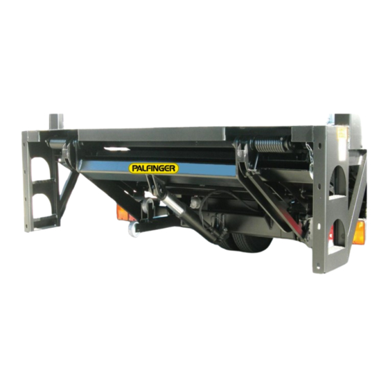
- Page 1 Model PLR Liftgate Single & Dual Cylinder, Gravity & Power Down Training, Troubleshooting & Maintenance REV-121621...
- Page 2 ALL MODELS OF PALFINGER LIFTGATES Installation, Operator(Owner) and Parts Manuals are available for download or viewing on our website at https://www.palfinger.com/en-US/usa/products/lift-gates. Additionally, troubleshooting guides, hydraulic and electrical schematics are available for download and/or viewing. Diagrams of decal placement are in the Installation and Operator Manuals. Decals are furnished at no cost to our customers.
- Page 3 ILT Serial Number Location...
- Page 4 PLR D SERIES LIFTGATE COMPONENTS DUAL CYLINDER...
- Page 5 PLR S SERIES LIFTGATE COMPONENTS SINGLE CYLINDER...
-
Page 6: Hydraulic Power Unit
Hydraulic Power Unit Hydraulic Power Unit Gravity Down Hydraulic Power Unit Power Down... -
Page 9: Check Battery Voltage
Basic Battery Conditions and Testing Proper voltage is key to proper liftgate operation. BEFORE YOU START TROUBLESHOOTING State of Charge –vs- Voltage CHECK BATTERY VOLTAGE State of Charge Open Circuit Voltage 10-10 TEST 100% 12.70V USING A MULTIMETER SET ON DC VOLTAGE: 12.60V OPEN LIFTGATE AND RAISE TO BED LEVEL. - Page 10 TRACTOR AND TRAILER CROSS TEST ON ENTIRE CHARGE SYSTEM Make sure King Pin Plate is grounded to side rail. Does Fifth Wheel have a ground strap to the tractor chassis?
- Page 11 PLR Electrical Components NOTE: Always use a digital voltmeter when checking voltage to determine if you have sufficient power to operate the liftgate. The liftgate should have a 150A Resettable Circuit Breaker and a 15A ATC Fuse in the electrical circuit set up. These were installed at the liftgate was mounted.
- Page 12 PLR Electrical Schematic Gravity Down...
- Page 13 PLR Electrical Schematic Power Down...
- Page 14 PLR Gravity Down Cylinder Components Bushing Inside Clevis Bushing Inside Clevis Grease Grease Zerk Zerk Hydraulic Hose with Fitting Restrictor Adaptor Threads in Solenoid Valve to port. Coil Power Cable for Hose Fitting Adaptor Restrictor Coil on Solenoid Valve Retainer Cap...
- Page 15 PLR Power Down Cylinder Components Bushings Inside Clevis Grease Zerk on Clevis Hydraulic Hose with Fittings Grease Zerk on Clevis Adaptor Restrictor Coil on Solenoid Valve Power Cable for Coil on Solenoid Valve Solenoid Valve Removed from Port - with Coil and Retainer Cap...
- Page 16 PLR Gravity Down-Hydraulic Schematic S1 & S2 - Release V alve for Lowering R1 & R2 - Flow Restrictor for limiting lower speed. Raise = M Lower = S1+S2 Dual Cylinder Option Lift Cylinder Lift Cylinder Pump Unit "A" "A"...
- Page 17 PLR Power Down-Hydraulic Schematic S1 & S2 - Release V alve for Lowering R1 & R2 - Flow Restrictor for limiting lower speed. S5 - Shift V alve is activated upon LOWER function only . Pilot to close check valve is NOT used on Power Down.
- Page 18 PLR Electric Schematic LOWER/GRAVITY DOWN Function LOWER/GRAVITY DOWN FUNCTION Toggle switch or hand held remote activated in LOWER/DOWN position. One (1) Lowering Solenoid valve on cylinder (S1) is Solenoid On energized. Cylinder Hydraulic fluid is released out of cylinder #6 Black Wire Lower/Down flowing into reservoir, lowering platform.
- Page 19 PLR Electric Schematic RAISE/LIFT Function RAISE/LIFT FUNCTION Toggle switch or hand held remote activated in RAISE/LIFT position. One (1) Lowering Starter Solenoid and Motor energized. Solenoid On Cylinder Hydraulic fluid is pumped through valve into cylinders raising platform. #6 Black Wire Lower/Down...
- Page 20 PLR Hydraulic Schematics for RAISE/LIFT and Lower/Gravity Down Functions RAISE/LIFT LOWER/GRAVITY FUNCTION DOWN FUNCTION Toggle switch or Toggle switch or hand held remote hand held remote activated in activated in RAISE/LIFT position. LOWER/DOWN position. Starter Solenoid and Solenoid valve on Motor energized.
- Page 21 MOTOR RUNS, GATE WON'T LOWER POWER DOWN 1. CHECK FOR POWER, GROUND AND PROPER OPERATION Main Liftgate OF S1, S2, AND S5 VALVES Cab Shut-Off Toggle Control Switch GATE LOWERS, MOTOR NOT RUNNING Power 1. CHECK FOR 12 VOLTS TO MOTOR RELAY FROM Load Raise DIODE IN POWER DOWN HARNESS...
- Page 22 Power Down = M + S1&S2 + S5 Lift Cylinder Lift Cylinder Power Down = M + S1&2 + S5 Pump Unit "B" "A" S1 & S2 - Release Valve for Lowering R1 & R2 - Flow Restrictor for limiting lower speed. S5 Shift Valve S5 - Shift Valve is activated upon LOWER function only.
- Page 23 MOTOR WON'T RUN WITH SWITCH IN UP POSITION CHECK THE FOLLOWING: RAISE 1. 12 VOLTS FROM 150 AMP CIRCUIT BREAKER AT BATTERY TO MOTOR SOLENOID Main Liftgate 2. 12 VOLTS FROM MOTOR SOLENOID TO CAB CUT-OFF SWITCH Toggle Control Switch Cab Shut-Off 3.
- Page 24 Raise = M Lift Cylinder Lift Cylinder Raise = M Power Down = M + S1&S2 + S5 Pump Unit "B" "A" S1 & S2 - Release Valve for Lowering R1 & R2 - Flow Restrictor for limiting lower speed. S5 Shift Valve S5 - Shift Valve is activated upon LOWER function only.
- Page 25 Power Cable to Release Valve Coil Test Check for broken power wire in release valve cable: • Unplug connector at valve. • Set multimeter to read DC voltage. • Put positive lead of multimeter in plug. • Put negative lead of multimeter in other hole of plug.
- Page 26 Release Valve Coil Test If one or both release valves on lift cylinders are not opening up, low voltage may be the cause. A minimum of 9V is necessary to properly energize each of the release valve coils. If the minimum voltage is present at both coils, the coil may not be generating the magnetism needed to open the release valve.
- Page 27 First Inspection, Lift Gate Condition 1) Damage to lift gate : Broken or Missing Parts . 2) Battery connections clean and tight , No corrosion. 3) Lift gate wiring clean and tight , No damage , No corrosion. 4) Burnt fuse , Tripped circuit breaker. 5) Pins greased , Hydraulic oil tank full.
-
Page 28: Troubleshooting Section
TROUBLESHOOTING SECTION BEFORE DOING 10 -10 TEST : 1. SHUT OFF TRUCK ENGINE. 2. UNHOOK CHARGE COIL FROM TRACTOR . 3. SHUT OFF BATTERY CHARGER . 4. DISCONNECT ANY OUTSIDE BATTERY SOURCE. CONFIRMING BATTERY VOLTAGE WITH 10 -10 TEST : USING A MULTIMETER , SET ON DC VOLTAGE . -
Page 29: Motor Not Running
LIFT GATE NOT WORKING HEAR NO SOLENOIDS CLICKING HEAR SOLENOIDS CLICKING 1. CHECK FUSES AT POWER PACK 1. CHECK CIRCUIT BREAKER AT BATTERIES 2. CHECK FOR BAD SWITCHES 2. GO TO : MOTOR NOT RUNNING 3. CHECK FOR BAD MOTOR SOLENOID BAD SOLENOID VALVE MOTOR NOT RUNNING 1. - Page 30 LIFT GATE NOT LIFTING MOTOR NOT RUNNING : Go to section in this manual on Motor Not Running LIFT GATE NOT LOWERING S-1 & S-2 VALVES ON LIFT CYLINDERS NOT OPENING (IF POWER DOWN CHECK S5 VALVE OPENING AND MOTOR RUNNING) LIFT GATE NOT LIFTING LOAD FIRST, ADD 12 VOLT POWER SUPPLY DIRECT TO BATTERIES SECOND, MOVE 12 VOLT POWER SUPPLY DIRECT TO MOTOR SOLENOID AND GROUND ON...
- Page 31 Maintenance and Care...
- Page 32 Lubrication PLR Dual Cylinder - 1. Lower the platform to the ground. 2. Remove red protector caps from each zerk. Lubricate, grease, and oil per diagram below. 3. Cycle platform up and down several times. Lubricate and grease all points again.
- Page 33 Lubrication PLR Single Cylinder - 1. Lower the platform to the ground. 2. Remove red protector caps from each zerk. Lubricate, grease, and oil per diagram below. 3. Cycle platform up and down several times. Lubricate and grease all points again.
-
Page 34: Checking And Changing Oil
Checking and changing oil Bleeding Hydraulic System All Palfinger Liftgates have Vented caps on Reservoir and will Push air in Hydraulic System back to Reservoir and out vented cap by just running the liftgate through normal cycles and keeping Hydraulic fluid at the... -
Page 35: Preventive Maintenance
PREVENTIVE MAINTENANCE Adjusting Pitch on Platform... - Page 36 PREVENTIVE MAINTENANCE Adjusting Platform Springs...
- Page 37 PREVENTIVE MAINTENANCE Adjusting Sliding Wheel...
- Page 38 PREVENTIVE MAINTENANCE Adjusting Rubber Snubbers...
- Page 39 5:00pm ET, Monday thru Friday Jorge Gallardo – Asst. Tech Support and Warranty Kim Loran- Parts Asst, Manager 609-587-4200 ext. 127 562-252-0407 K.loran@palfinger.com j.gallardo@palfinger.com Ben Styer – Parts Asst. / Technical Support Rey Rodriguez – Parts Asst. 609-587-4200 ext. 126 562-252-0410 b.styer@palfinger.com...
Need help?
Do you have a question about the PLR and is the answer not in the manual?
Questions and answers