Table of Contents
Advertisement
Quick Links
Advertisement
Table of Contents

Related Manuals for Hadeco Bidop 7


Summary of Contents for Hadeco Bidop 7
-
Page 2: Table Of Contents
TABLE OF CONTENTS Cautions 1. Introduction ........................1 1-1. Features ........................2 1-2. Clinical applications ....................2 2. Appearance ........................3 2-1. Front view ........................ 3 2-2. Operating panel ....................... 4 2-3. Probe ........................5 3. How to use ........................6 3-1. - Page 3 8-3. Specifications ......................24 8-4. Safety standards ....................25...
- Page 5 Cautions Please read the following important points carefully before you operate the unit. 1. Only skilled persons should operate the unit. 2. Use the unit for measuring blood flow. 3. Do not apply any modification to the unit. 4. Device placement (1) Follow the requirements for storage and operating environments.
- Page 6 (3) Always make sure the unit and patient are not under abnormal conditions. (4) When any abnormality is found on the unit or the patient, take proper action such as stopping operating the unit in a manner safe to the patient.
- Page 7 11. Ultrasonic gel (1) Do not apply ultrasonic gel to the probe body other than the tip of probe. (2) Using other materials may damage the probe. (3) The ultrasonic gel enclosed is non-sterile and do not use it for surgeries.
-
Page 8: Introduction
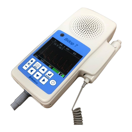
1. Introduction Thank you very much for choosing the Bidop 7. The Hadeco Bidop 7 is a uniquely designed bi-directional Doppler with color LCD display. It detects arterial and venous blood flow in extremities. The Bidop 7 displays velocity waveform and numerical data. -
Page 9: Features
Displays real-time waveforms, numerical data on color LCD. NEWLY ADVANCED GREAT SOUNDS Highly sensitive “ST” probes enhance the Hadeco sensitivity with wider Doppler beam for 4, 5, 8, & 10 MHz Optimized volume control for a whole range of low to high flow. -
Page 10: Appearance
2. Appearance 2-1. Front view Headset connector To connect your own headset. It cuts off the speaker To operate the unit Operating panel See “§2.2 Operating panel” for the details. Serial port To connect computer (USB) Probe connector To connect probe AC adaptor connector To connect AC adaptor Strap holes... -
Page 11: Operating Panel
2-2. Operating panel To adjust sound volume; Volume : To turn the volume UP. control button : To turn the volume DOWN. Press it longer than 1 sec to mute the unit. Menu button To get to and get out of MENU mode. Up / Down To select menu item. -
Page 12: Probe
2-3. Probe Probe cap To protect the transducer tip when not in use. Doppler transducer To detect blood flow. To freeze and unfreeze the waveform & numerical Probe button data. -
Page 13: How To Use
3. How to use 3-1. Preparation 3-1-1. Charging the battery (1) Press Power button to turn the unit OFF. (2) Plug the AC adaptor to the unit to charge the battery. Note: Use the designated AC adaptor. Model name: GMPU18EI-3 AC adaptor connector “CHARGING”... -
Page 14: Connecting Probe
3-1-3. Connecting probe Connect the probe to the Bidop so that the PIN key of probe connector goes into the GROOVE key at 6 o’clock of the Bidop connector. Note: Make sure to push the connector all the way until it clicks for connection. Hold the Bidop and straight pull the base of connector for disconnection. -
Page 15: Measurement
3-2. Measurement 3-2-1. Blood velocity mode This section explains the fundamental use of measuring blood velocity. (1) Put ultrasonic gel on the patient skin. (2) Put the probe on the measurement area and move it slowly to locate the point where the maximum Doppler sounds are heard. - Page 16 To store the data If you wish to store the waveform and numerical data on the memory, do the following procedures. (1) Press and go to MEMORY menu. (2) Select STORE and next memory number available for storage will be displayed as shown in the right.
-
Page 17: Site Guidance Mode
3-2-2. Site guidance mode This mode allows you to easily proceed multiple Smart-V-Link testing by just pressing probe button without connecting Smart-V-Link. Register Abbreviated site & test names on the unit through Smart-V-Link to activate this mode. Once the names are registered, the unit will show each of names at the beginning of each testing to let you know where to test next. - Page 18 Site guidance mode procedures (1) Turn the unit off and on and the 1 guidance with memory number and abbreviated site & test name will appear as shown in the right. Note: The first memory number available will Memory number be selected automatically.
-
Page 19: Ppg Waveform Studies
3-2-3. PPG waveform studies With the PPG probe, PG-30 (Option), the Bidop senses the reflection of light from the hemoglobin of the red blood cells in surface vessels by utilizing infrared light. This section explains the fundamental use of measuring PPG, photoplethysmograph. - Page 20 Preparation: (1) Connect the PPG probe to the unit and turn it on. MENU (2) Go to MODE menu and set it for AC. MODE (3) Check that the face of the PPG sensor is free of stains. Clean it if necessary. Examination Procedure: (1) Apply the sensor with the clear side against the skin surface, and fix it in...
- Page 21 PPG - Venous Reflux Study Purpose: The venous reflux study is performed to assess valvular competence by measuring the amount of time required for venous refilling after calf veins have been emptied through exercise. Preparation: (1) Connect the PPG probe to the unit and turn it on.
- Page 22 (4) Ask the patient to flex the foot specified number on COUNT following the foot animation and beep on Bidop. The exercise should be forceful, especially when lifting the foot upward. (5) After flexing, instruct the patient to relax the foot and avoid all movement. (6) The test is completed when the waveform returns to the baseline and Bidop will automatically freeze the...
-
Page 23: Menu And Mode Settings
4. Menu and Mode settings Various mode settings can be selected on MENU mode. Some of the menus consist of sub-menu(s). ENTER MENU LEFT RIGHT DOWN < Operating panel > 4-1. Menu operation Press to show the MENU depending on Basic mode. -
Page 24: Menu For Blood Velocity Mode
4-2. MENU for Blood Velocity mode Selections in bold face in the table are default settings. Menu Sub Menu Selections M/F* Reference Section#. STORE 1 to 30, FREEZE MEMORY READ 1 to 30, FREEZE §3-2-1 CLEAR 1 to 30, ALL COMPOUND MODE SEPARATION... -
Page 25: Menu For Ppg Ac/Dc Mode
4-3. Menu for PPG AC/DC mode Menu Sub Menu Selections M/F* Reference Section#. STORE 1 to 30, FREEZE READ 1 to 30, FREEZE MEMORY §3-2-1 CLEAR 1 to 30, ALL MODE AC, DC §3-2-3 COUNT 1 to 20 (DC mode only) FREEZE MANUAL, AUTO OTHERS... -
Page 26: Menu And Mode Settings Details
4-4. MENU and Mode settings details Symbol/ Selections Description Menu Combined forward and reverse components Compound MODE (Waveform mode) Separation Separation of forward from reverse component Flow toward probe is processed as positive Forward component. Flow away from probe is processed as positive (Flow direction) Reverse component. -
Page 27: Maintenance
5. Maintenance 5-1. Performance check by user Perform the following performance checks at least once a year: (1) Make sure if there is no damage and/or crack on the main unit and probe. (2) Shake the main unit and make sure if there are no sounds inside from internal components coming off. -
Page 28: Supplemental Information
6. Supplemental information 6-1. Numerical data Parameters Abbr. Definitions Systolic velocity [cm/s] or systolic Doppler shift [kHz] Mean velocity [cm/s] or mean Doppler shift [kHz] Diastolic velocity [cm/s] or diastolic Doppler shift [kHz] Minimum velocity [cm/s] or minimum Doppler shift [kHz] RP = (S -D) / S Resistance Parameter RP = 1 if waveform goes blow base line. -
Page 29: Options
7. Options 7-1. Probe selection Standard Doppler probe: ST8M05S8C (8MHz) PPG probe: PG-30 7-2. Others Smart-V-Link software with communication cable... -
Page 30: Technical Information
8. Technical information 8-1. Principles Model Bidop 7 is designed to obtain various blood flow velocity through the ultrasound which is transmitted from probe to patient body and is reflected by the blood (hemocyte, etc.). The unit amplifies the high frequency oscillation output and then supplies it to the transmitter transducer. - Page 31 8-3. Specifications Probes: Frequency: Acoustic power Ispta* (in situ): 4, 5, 8 and 10MHz 720 [mW/cm²] or less * Ispta: Special Peak-Temporal Average Intensity. AC adaptor: Model name: GMPU18EI-3 Power: Input: AC 100-240V, 50/60Hz Output: DC 12V, 1A or more Consumption: DC 12 V, 550 mA MAX.
- Page 32 Edition) Guidance and manufacturer’s declaration – electromagnetic emissions The Bidop 7 is intended for use in the electromagnetic environment specified below. The customer or the user of the Bidop 7 should assume that it is used in such an environment.
- Page 33 Guidance and manufacturer’s declaration – electromagnetic immunity The Bidop 7 is intended for use in the electromagnetic environment specified below. The customer or the user of the Bidop 7 should assure that it is used in such an environment. Immunity test...
- Page 35 For European Union Countries: European Authorized Representative ICHIYAMA GmbH Benderstraße 130, 40625 Düsseldorf, Germany Tel: 0211-298538 Fax: 0211-299257...
- Page 36 Manufactured by Hadeco, Inc. 0123 2-7-11 Arima, Miyamae-ku, November, 2018 Kawasaki, Kanagawa Printed in Japan 216-0003 Japan 080-00212-1.0...
Need help?
Do you have a question about the Bidop 7 and is the answer not in the manual?
Questions and answers