Table of Contents
Advertisement
Quick Links
Advertisement
Table of Contents

Related Manuals for Hadeco Smartdop 45


Summary of Contents for Hadeco Smartdop 45
-
Page 2: Table Of Contents
TABLE OF CONTENTS Cautions 1. Introduction ........................1 1-1. Features........................1 1-2. Clinical applications....................3 1-3. Probe selection ......................3 1-4. Contents of package ....................4 2. Quick start ........................5 2-1. Turning the unit ON / OFF..................5 2-2. Charging / Discharging battery..................6 2-3. Checking battery level....................7 2-4. - Page 3 q. OTHERS - KEYBOARD (External)..............27 r. OTHERS - P.ID PRT (Patient data print) ..............27 s. OTHERS - PRB-KEY (Probe button function) .............27 t. OTHERS - DATE (Date and time setting).............27 u. OTHERS - PRINT (Printer activation) ..............27 3-3. LCD display......................28 3-3-1.
- Page 4 CAUTIONS Please read the following important points carefully before you operate the unit. 1. Only skilled persons should operate the unit. 2. Use the unit for measuring blood flow. 3. Do not apply any modification to the unit. 4. Device placement (1) Follow the requirements for storage and operating environments.
- Page 5 (10) Do not use the unit in a strong electromagnetic field or it may cause incorrect measurements. 7. After use: (1) Turn the unit off the way specified. (2) Do not pull the cable(s) too much while disconnecting or it may cause damage. (3) Clean the unit, AC adaptor, cables and probes and place them in right place for the next use.
- Page 6 14. Repair services (1) When the unit gets out of order, contact the dealer for repair from whom you purchased the unit. (2) Only authorized persons should perform the repair services. 15. Do not disassemble the unit. 16. Destruction (1) In case of destruction of the unit, follow the instructions for disposal of the destruction appointed by each country or local government.
-
Page 7: Introduction
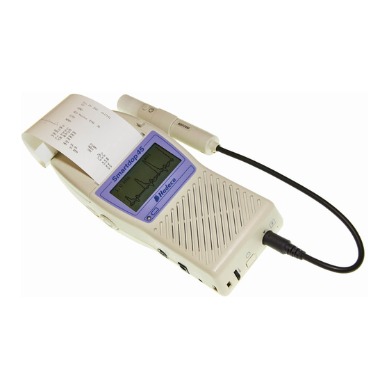
1. Introduction Thank you very much for choosing the Smartdop 45. The Hadeco Smartdop 45 is a uniquely designed bi-directional handheld Doppler with LCD display and fast printer. It detects arterial and venous blood flows in extremities as well as fetal heart sounds. - Page 8 Communication cable and Windows software are optional. * PHOTOPLETHYSMOGRAPH (PPG) AND PNEUMOPLETHYSMOGRAPH (PV) PROBES OPTIONAL Expands arterial & venous testing.
-
Page 9: Clinical Applications
The frequency of diagnostic ultrasound is inversely proportional to depth of penetration. The Smartdop has 5 interchangeable probes with different frequencies. Use those probes depending on your applications. Note: One of these probes comes with Smartdop 45 as a standard accessory. Other probes are available as optional accessories. BT2M20S8C (2 MHz):... -
Page 10: Contents Of Package
1-4. Contents of package Main unit Probe AC adaptor Ultrasonic gel Paper Carrying case... -
Page 11: Quick Start
2. Quick start For the first time of use and in case the unit has been not used for a while, fully charge the internal battery. 2-1. Turning the unit ON / OFF (1) Connect the probe to the probe connector so that Polarity mark the polarity mark will be placed under... -
Page 12: Charging / Discharging Battery
(5) AUTOMATIC POWER OFF When the AUTO-OFF mode is ON, if the unit is left on, the power is automatically shut off after following time passes: (a) 35 minutes when in measurement. (Only Fetal Heart Rate WAVE mode) (b) 15 minutes when in measurement. (Except Fetal Heart Rate WAVE mode) (c) 5 minutes when no signal. -
Page 13: Checking Battery Level
• The “DISCHARGE” will be displayed on the LCD. • After the discharging completed, charge process will start automatically and the “DISCHARGE” will disappear, then charging indicator will go solid orange. Note: It takes about 3 hours to fully charge battery. Battery life is 300 full charges. -
Page 14: Setting Printer Paper
Date setting, and Patient data excluding other Menu mode settings. (1) Press Enter button to go to Measurement mode and charge the battery. 2-4. Setting printer paper (1) Press Cover Open Button to open the paper Roll shaft cover and remove the roll shaft. (2) Insert the roll shaft into the paper roll. -
Page 15: Measuring Blood Velocity
2-5. Measuring blood velocity This section explains the fundamental use of measuring blood velocity. Refer to “3. Appearance and Mode Settings” for various uses. (1) Connect the probe to the probe connector so that Polarity mark the polarity mark will be placed under mark as shown in the right (12 o’clock). -
Page 16: Measuring Fetal Heart Rate (2 Mhz Only)
(6) Headset (Option) can be used to listen to Doppler sounds. It will cut off the speaker. Headset connector 2-6. Measuring fetal heart rate (2 MHz only) This section explains the fundamental use of measuring fetal heart rate. Refer to “3. Appearance and Mode Settings”... - Page 17 (6) When the heart rate becomes stable, press the probe button or Right button to freeze it. Note: If the stable signals are not being detected, the “*” mark will be shown above “HR”. (7) Headset (Option) can be used to listen to Doppler sounds.
-
Page 18: Appearance And Mode Settings
3. Appearance and mode settings 3-1. Operating controls 3-1-1. Front left view <Scroll Button> Back Button 1. Paper cover: For printer paper. 2. Cover Open Button To open the paper cover. 3. LCD display: Displays waveform, numerical data, heart rate and menu for mode settings. - Page 19 10. AC adaptor connector: To connect the designated AC adaptor. 11. Keyboard connector: To connect PS2 keyboard, optional. 12. Charging indicator: Indicates battery status. Orange : Charging Green : Fully charged 13. Scroll Button: Consists of 5 internal buttons and has following functions.
- Page 20 3-1-2. Front right view and Probe 1. Probe holder: For probe placement when not in use. 2. Communication port: To connect computer. (USB) 3. Probe: Multi-probe selection of 2, 4, 5, 8 and 10 MHz 4. Probe button: To freeze and unfreeze the waveform. To activate and deactivate the printer.
-
Page 21: Mode Settings
3-2. Mode settings Note: For the mode settings for options, see “§ 5-2-5. Menu for PPG” and “§ 5-3-5. Menu for PV”. 3-2-1. Basic Modes Smartdop has following five Basic Operation Modes: • Blood Velocity - Measurement For measuring blood velocity •... -
Page 22: Menu
3-2-2. Menu Using Scroll Button, various mode settings are changeable on Menu mode. Some menus have sub menus. Refer to following Menu structure and Menu operation first. a. Menu structure 2 MHz only only b. Menu operation (1) Press Enter to show MENU depending on Basic <Scroll Button>... - Page 23 (3) For MEMORY, PATIENT and OTHERS in MENU, pressing Enter or Right button shows sub menu for further mode settings. (4) For MEMORY sub menus and LANGUAGE, press Up or Down button again for the selection of memory number or language. (5) Press Left button to go back to main menu from submenu or get out of the menu mode.
-
Page 24: Menu For Blood Velocity Measurement Mode
c. Menu for Blood Velocity Measurement mode Menu Sub Menu Selections Reference in §3-2-3. STORE 1 to 30, FREEZE a. Memory - Store MEMORY READ 1 to 30, FREEZE b. Memory - Read CLEAR 1 to 30, ALL c. Memory - Clear MODE (waveform) d. -
Page 25: Menu For Blood Velocity Freeze Mode
d. Menu for Blood Velocity Freeze mode Menu Sub Menu Selections Reference in §3-2-3. STORE 1 to 30, FREEZE a. Memory - Store MEMORY READ 1 to 30, FREEZE b. Memory - Read CLEAR 1 to 30, ALL c. Memory - Clear MODE (waveform) d. -
Page 26: Menu For Fetal Heart Rate Mode (Measurement And Freeze)
e. Menu for Fetal Heart Rate mode (Measurement and Freeze) Menu Sub Menu Selections Reference in §3-2-3. STORE 1 to 30, FREEZE a. Memory - Store MEMORY READ 1 to 30, FREEZE b. Memory - Read CLEAR 1 to 30, ALL c. -
Page 27: Mode Setting Details
3-2-3. Mode Setting Details See "§ 3-2-2-b. Menu operation" for button operation on Menu mode. Do the mode setting once and subsequent Smartdop use will revert to this mode. However, if battery gets extremely low, memory data will be cleared for waveform data, Date setting, and Patient data excluding other Menu mode settings. -
Page 28: Memory - Clear
Note: Any frozen waveform is stored temporarily in memory area of FREEZE separated from regular 30 memory. It can be re-shown by reading from memory FREEZE and won't be erased until next waveform is frozen or unit is turned off. c. -
Page 29: Time (Time Scale)
e. TIME (Time scale) (1) Press Enter to change the time scale as follows: Normal: For arteries (2.56 sec/screen) Slow: For veins (12.8 sec/screen) f. DIR (Flow direction) (1) Press Enter button to change waveform polarity as follows: Forward: Flow toward probe is processed as positive component. Reverse: Flow away from probe is processed as positive component. -
Page 30: Upper (Upper Limit For Fhr)
h. UPPER (Upper limit for FHR) If heart rate exceeds the upper limit for more than 30 sec, LCD will start flashing for warning. (1) Press Up and Down to select the upper limit in 5 BPM steps and press the button to fix it. - Page 31 (2) Scroll to the letter you wish and press Enter to Screen keyboard type it. Pressing Back Button or entering Backspace ( ) deletes the letter you typed previously. (3) After entering the data, press and hold Print/Back for longer than 1 sec to save the data or scroll to (Back) and press Enter to do it.
-
Page 32: Others - Language
k. OTHERS - LANGUAGE (1) Press Up and Down to select the language in which menus and messages are written. And press Enter to fix it. l. OTHERS - UNIT (cm/s / kHz) (1) Press Enter to change the unit of blood flow as follows: cm/s: Blood flow velocity kHz:... -
Page 33: Others - Keyboard (External)
q. OTHERS - KEYBOARD (External) (1) Press Enter to change the keyboard. ENGLISH: 104 English keyboard PS2 JAPANESE: 109 Japanese keyboard PS2 Note: Only PS2 keyboard is available. r. OTHERS - P.ID PRT (Patient data print) (1) Press Enter to change the mode as follows: Prints with patient data. -
Page 34: Lcd Display
3-3. LCD display 3-3-1. Blood Velocity Mode Waveforms (1) The base line is automatically located at optimal position for each waveform. Smartdop has 4 base lines, the bottom, 1/4 from the bottom, the center, and 3/4 from the bottom. (2) The waveform amplitude is automatically adjusted for optimal observation. (3) The amplitude scale (velocity or frequency per division) is displayed on top left of LCD. -
Page 35: Fetal Heart Rate (Fhr) Mode (Only 2 Mhz Probe)
Numerical data Following numerical parameters are displayed on DATA mode. Unit: cm/s Unit: kHz See “3-5. Numerical Data” for the meaning of abbreviations and the definitions of parameters. 3-3-2. Fetal Heart Rate (FHR) mode (Only 2 MHz probe) Displaying heart rate at the moment (DATA mode) (1) Heart rate is displayed based on a 4 beat average once the Smartdop gets sufficient data to calculate. - Page 36 Monitoring heart rate in graph (WAVE mode, Monitoring mode) (1) The measurement range of heart rate is 60 to 220 BPM. (2) Heart rate at the moment is displayed on bottom left of LCD. FHR monitoring waveform Heart rate Upper Lower Measuring Heart rate at the moment...
-
Page 37: Printing Waveforms And Data
3-4. Printing waveforms and data 3-4-1. The mode settings influencing printed chart The following mode settings influence the printed waveform and data. Smartdop prints depending on the present mode settings. Change modes before printing if desired. Note: Refer to the description of each mode in “ 3-2-3. Mode Setting Details”. Mode Abbrev. - Page 38 FHR mode Monitoring mode: Waveform of up to the 33 minutes before freezing (3) Press Print button or execute PRINT command the second time to deactivate the printer. 3-4-3. Print sample Unit Patient data Time scale area Direction Numerical Waveform data area mode Waveform...
-
Page 39: Numerical Data
3-5. Numerical data Parameters Abbrs. Definitions Systolic velocity [cm/s] or Systolic Doppler shift [kHz] Mean velocity [cm/s] or Mean Doppler shift [kHz] Diastolic velocity [cm/s] or diastolic Doppler shift [kHz] Minimum velocity [cm/s] or minimum Doppler shift [kHz] Resistance Parameter RP=(S-D) / S RP=1 if waveform goes below base line. -
Page 40: External Outputs
3-6. External outputs 3-6-1.Headset Connect the headset when necessary. The headset cuts off the speaker. See 3-1. Operating Controls. 3-6-2. Communication port (3.5 mm jack) To observe the waveform in high resolution on a PC monitor or to store the waveform and numerical data into a computer for future reference as well as an entire report for standardized testing modules. -
Page 41: Maintenance
4. Maintenance 4-1. Performance check by user Perform the following performance checks at least once a year: (1) Make sure if there is no damage and/or crack on the main unit and probe. (2) Shake the main unit and make sure if there are no sounds inside from internal components coming out. -
Page 42: Options
you purchased the unit. In case the warranty period is over, please consult the dealer for a charged service. *1: Guarantee period of ACP-08: either one year from the date of purchase or within 5 times of autoclave sterilization. 5. Options 5-1. - Page 43 Warnings Sterilizable probes are not sterilized before shipment. They must be sterilized before use as follows: Sterilization limits 1. All sterilizable probes except ACP probe: Up to 50 times 2. ACP probe: Up to 5 times (steam autoclave) Note. Do not exceed sterilization limits or it may cause damage to probes. Caution 1.
- Page 44 Packaging: No particular requirements. Storage: No particular requirements. Manufacturer contact: Hadeco, Inc. 2-7-11 Arima, Miyamae-ku, Kawasaki, 216-0003, Japan Tel: +81-44-877-4361 Fax: +81-44-855-7301 The instructions provided above have been validated by the medical device manufacturer as being CAPABLE of preparing a medical device for reuse. It remains the responsibility of the processor to ensure that the processing as actually performed using equipment, materials and personal in the processing facility achieve the desired result.
-
Page 45: Photoplethysmograph
5-3. Photoplethysmograph With the PG-21 and PGV-20 (PPG mode), Smartdop senses the reflection of light from the hemoglobin of the red blood cells in surface vessels by utilizing infrared light. Basically, “How to use photoplethysmograph” is described in this section. For other matters such as Cautions, Technical information and Interpretations of test result, refer to the Operating Manual that comes with your PPG probe. - Page 46 5-3-3. PPG - Arterial Pulse Waveform Studies Purpose Arterial pulse waveform studies by photoplethysmography are performed to determine the presence or absence of pulsatile flow and to assess the state of perfusion in the tissue area immediately beneath the sensor site. When used with a suitable cuff and manometer, the method permits the measurement of systolic blood pressure in the fingers and toes.
- Page 47 Examination Procedure (1) Apply the sensor with the clear side against the skin surface, and fix it in place using Velcro straps or double-sided clear tape. (2) If you wish to input patient data, see “3-2-3-j. PATIENT”. (3) The gain is automatically adjusted and the PPG waveform is shown on the LCD.
- Page 48 Note: With the PGV-20 probe, set the PPG/PV mode switch to the PPG mode beforehand. (2) Press Enter button to display MENU. Scroll to MODE and press Enter to change from AC to DC mode. (3) COUNT represents number of foot exercise during study and if desired, press Enter on COUNT and press Up and Down to change the number.
- Page 49 (4) Press Right or probe button to begin the measurement process. (5) Ask the patient to flex the foot specified number on COUNT following the foot animation on LCD. The exercise should be forceful, especially when lifting the foot upward. (6) After flexing, instruct the patient to relax the foot and avoid all movement.
- Page 50 5-3-5. Menu for PPG Menu Sub Menu Selections Reference in §3-2-3 STORE 1 to 30, FREEZE a. Memory - Store MEMORY READ 1 to 30, FREEZE b. Memory - Read CLEAR 1 to 30, ALL c. Memory - Clear MODE(Coupling) 5-3-6.
-
Page 51: Pneumoplethysmograph
5-4. Pneumoplethysmograph With the PGV-20 (PV mode), Smartdop senses volume changes in a limb or digit by measuring the pressure changes in a recording cuff. Basically, “How to use pneumoplethysmograph” is described in this section. For other matters such as Cautions, Technical information and Interpretations of test result, refer to the Operating Manual comes with your PV probe assembly. - Page 52 Preparation (1) Connect the PV probe to the main unit, and turn it on. Note: With the PGV-20 probe, set the PPG/PV mode switch to the PV mode beforehand. Power button (2) Press Enter button to display MENU and make sure MODE is on AC mode.
- Page 53 (6) Inflate the cuff to 60 mmHg. Then, turn the stopcock so that it blocks the sphyg and routs cuff pressure to the PV interface box. (7) The gain is automatically adjusted and the PV waveform is shown on the LCD. (8) When the waveform gets stable and rhythmic, press the Right to freeze the waveform.
- Page 54 (2) Press Enter button to display MENU. Scroll to MODE and press Enter to change from AC to DC mode. Examination Procedure (1) Place the patient in supine position with the leg and hip rotated outward. Use pillows to support the leg and hip. It is important that the patient is comfortable and relaxed. (2) Wrap a wide occluding cuff at mid-thigh and a sensing cuff at mid-calf.
- Page 55 (10) Inflate the occluding cuff at the thigh to at least 60 mmHg. Pressures in the cuff are plotted on the screen. The graph will indicate a gradual increase in waveform amplitude signifying that venous outflow is blocked by the occluding cuff. (11) After 90 seconds, disconnect the sphyg from the occluding cuff.
- Page 56 5-4-5. Menu for PV Menu Sub Menu Selections Reference in §3-2-3 STORE 1 to 30, FREEZE a. Memory - Store MEMORY READ 1 to 30, FREEZE b. Memory - Read CLEAR 1 to 30, ALL c. Memory - Clear MODE(Coupling) 5-3-6.
-
Page 57: Technical Information
6. Technical information 6-1. Principles Model Smartdop 45 is designed to obtain various blood flow velocity through the ultrasound which is transmitted from probe to patient body and is reflected by the blood (hemocyte, etc.). The unit amplifies the high frequency oscillation output and then supplies it to the transmitter transducer. -
Page 58: Block Diagram
6-2. Block diagram... -
Page 59: Specifications
6-3. Specifications Probes: Model Freq. Ispta* (in situ) [mW/cm²] 80 mW/cm ² or less BT2M20S8C 2 MHz 390 mW/cm ² or less BT4M05S8C 4 MHz 390 mW/cm ² or less BT5M05S8C 5 MHz 390 mW/cm ² or less BT8M05S8C 8 MHz 390 mW/cm ²... - Page 60 External outputs: Headset, USB port Electrical safety: Conform to IEC60601-1 Internally powered equipment Type BF applied part. Operating environment: 10 to 40 degrees Centigrade 85% humidity or less with no condensation Storage and transport environment: 0 to 50 degrees Centigrade 85% humidity or less with no condensation Dimensions: Main unit:...
-
Page 61: Safety Standards
Guidance and manufacturer’s declaration – electromagnetic emissions The Smartdop 45 is intended for use in the electromagnetic environment specified below. The customer or the user of the Smartdop 45 should assume that it is used in such an environment. Emissions test... - Page 62 Guidance and manufacturer’s declaration – electromagnetic immunity The Smartdop 45 is intended for use in the electromagnetic environment specified below. The customer or the user of the Smartdop 45 should assure that it is used in such an environment. Immunity test...
- Page 63 Guidance and manufacturer’s declaration – electromagnetic immunity The Smartdop 45 is intended for use in the electromagnetic environment specified below. The customer or the user of the Smartdop 45 should assure that it is used in such an environment. Immunity test...
- Page 64 Manufactured by Hadeco, Inc. SD45 OM E-24 June, 2013 2-7-11 Arima, Miyamae-ku, Kawasaki, Printed in Japan 216-0003 Japan 080-00095-2.4...
Need help?
Do you have a question about the Smartdop 45 and is the answer not in the manual?
Questions and answers