Table of Contents
Advertisement
Quick Links
Advertisement
Table of Contents

Related Manuals for iseg MICC


Summary of Contents for iseg MICC
- Page 1 Technical documentation Last changed on: 2024-06-18 MICC CONTROLLER MMC SYSTEM CONTROLLER CAN, USB and Ethernet interfaces • 16 analog output with 20 Bit DAC resolution • 32 analog inputs with 24 Bit ADC resolution • 24 digital I/O ports •...
-
Page 2: Document History
Copyright © 2024 by iseg Spezialelektronik GmbH / Germany. All Rights Reserved. This document is under copyright of iseg Spezialelektronik GmbH, Germany. It is forbidden to copy, extract parts, duplicate for any kind of publication without a written permission of iseg Spezialelektronik GmbH. This information has been prepared for assisting operation and maintenance personnel to enable efficient use. -
Page 3: Safety
CAUTION! Advice marked as “Caution!” describe actions to avoid possible damages to property. INFORMATION Advice marked as “Information” give important information. Read the manual. Important information. Attention high voltage! MICC CONTROLLER | Last changed on: 2024-06-18 | www.iseg-hv.com 3/23... -
Page 4: Intended Use
You may only put the product into operation after it has been established that the high-voltage device complies with the • country-specific regulations, safety regulations and standards of the application. The high-voltage power supply unit may only be installed by qualified personnel. • MICC CONTROLLER | Last changed on: 2024-06-18 | www.iseg-hv.com 4/23... -
Page 5: Important Safety Instructions
When controlling, with software, the high voltage systems, make sure that nobody is near the high voltage or can be injured. INFORMATION Please check the compatibility with the devices used. MICC CONTROLLER | Last changed on: 2024-06-18 | www.iseg-hv.com 5/23... -
Page 6: Table Of Contents
8.4 External Inhibit 8.5 MICC CAN bus coupling 8.6 Status LEDs User Calibration Dimensional drawings Connectors and pin assignments Accessories Order guides References Glossary Warranty & service Disposal Manufacturer contact MICC CONTROLLER | Last changed on: 2024-06-18 | www.iseg-hv.com 6/23... -
Page 7: General Information
1 General information The universal MICC (Multichannel Interface Crate Controller) interface board connects the analog ports of MMC HV modules in 3U cassettes (CPS, DPS, EPS) with digital standard interfaces. Available interfaces are CAN bus (at the 96-pin connector according to DIN 41612), USB and Ethernet. -
Page 8: Overview
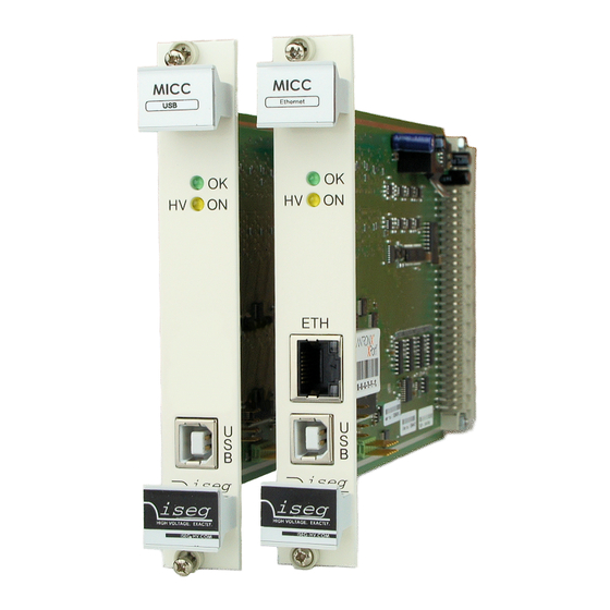
OK LED (green) Status LED 8.6 Status LEDs HV-ON LED (yellow) Status LED 8.6 Status LEDs ETHERNET Ethernet Interface 8.3 Ethernet Interface USB Interface 8.2 USB Interface Table 1: Overview MICC CONTROLLER | Last changed on: 2024-06-18 | www.iseg-hv.com 8/23... -
Page 9: Package Contents
MICC MICC controller See chapter 12 MICCETH Table 2: Package contents 4 Compatibility The MICC controller can be used in the following MMC crates: SYSTEM NUMBER OF SLOTS LIMITATIONS ECH 124 Full V capability ECH 128 Full V... -
Page 10: Technical Data
On 96-pin MMC connector resp. crate back panel For ECH 12A and 14A, I is preset to I of the corresponding HV-module, i.e. no adjustable constant current mode is possible. Table 5: Technical data MICC CONTROLLER | Last changed on: 2024-06-18 | www.iseg-hv.com 10/23... -
Page 11: Operation
7 Operation 7.1 Operation principle The heart of the MICC is the Microcontroller CPU. It combines the digital interfaces (CAN, USB, Ethernet) with the analog-to-digital and digital-to-analog components, as shown in the following schematic diagram. Figure 3: MICC schematic diagram MICC CONTROLLER | Last changed on: 2024-06-18 | www.iseg-hv.com... -
Page 12: Control
Disconnect the device from the mains before starting any work. Do not open the housing of the unit! INFORMATION The MICC user calibration has to be confirmed on every power-on with the HV_OK command. As long as the calibration is not confirmend, the OK LED is double-flashing (on-off-on-long off). The confirmation can be done... -
Page 13: Interfaces
The MICC is using the iseg EDCP CAN protocol and can be used in combination with other iseg devices on one CAN bus. It is important that the MICC is using a CAN address in the range 0...63 that is not used by another device on this CAN bus. The factory default address is 0 and can be changed with the SCPI command :CONF:CAN:ADDRESS. -
Page 14: Ethernet Interface
8.3 Ethernet Interface The 100 Bit/s full duplex Ethernet interface is available at a RJ-45 socket at the MICC front panel. The Ethernet interface is implemented by a Lantronix XPort hardware with a serial connection to the microcontroller. The Ethernet interface can be used to send SCPI commands through a raw TCP socket on port 10001. -
Page 15: Micc Can Bus Coupling
8.5 MICC CAN bus coupling As a special configuration, it is possible to connect multiple MICC over CAN bus and control all of them via one Ethernet connection to the first MICC at CAN address 0. For more information about such setups, contact the iseg support. See chapter 18 Manufacturer contact. -
Page 16: User Calibration
For more information refer to the SCPI or EDCP-CAN manual, see 14 References. The user calibration can be done with the program iseg MICC Config and an USB connection from the computer to the MICC. The procedure is described on the following pages. - Page 17 The following user calibration steps are only needed, when a MMC HV module was added, removed or exchanged or when a MICC is put in a crate for the first time. For the confirmation of the user calibration use the HV_OK command as described above.
- Page 18 Figure 6: A sample configuration INFORMATION The checkbox “Control external modules connect by CAN bus” is a customer specific extension. For further information contact the support, see 18 Manufacturer contact. MICC CONTROLLER | Last changed on: 2024-06-18 | www.iseg-hv.com 18/23...
-
Page 19: Dimensional Drawings
10 Dimensional drawings Figure 7: MICC with USB Figure 8: MICC with Ethernet MICC CONTROLLER | Last changed on: 2024-06-18 | www.iseg-hv.com 19/23... -
Page 20: Connectors And Pin Assignments
Figure 10 Table 9: Connectors and pin assignment 12 Accessories CAUTION! Only use genuine iseg parts like power cables, CAN cables and terminators for stable and safe operation. ACCESSORY ITEM ORDER ITEM CODE USB cable USB-A plug to USB-B plug, 0.5m... -
Page 21: References
SCPI control https://iseg-hv.com/download/?dir=SOFTWARE/isegSCPIcontrol/ CAN HV control https://iseg-hv.com/download/?dir=SOFTWARE/isegCANcontrol/ MICC config https://iseg-hv.com/download/?dir=SOFTWARE/isegMICCconfig/ FTDI-USB-Serial-Driver https://iseg-hv.com/download/?dir=SOFTWARE/Tools/ Lantronix / XPORT Device Installer https://www.lantronix.com/products/xport/ direct download link https://ltrxdev.atlassian.net/wiki/spaces/LTRXTS/pages/106070471/Latest%2Bversion%2Bof%2BDeviceInstaller EDCP https://iseg-hv.com/download/?dir=SOFTWARE/isegEDCP ISEG Control 1 https://iseg-hv.com/download/?dir=SOFTWARE/isegControl Table 12: References MICC CONTROLLER | Last changed on: 2024-06-18 | www.iseg-hv.com 21/23... -
Page 22: Glossary
HV ON HV OFF channel(s) high voltage low voltage signal ground Inhibit Polarity KILL KillEnable Table 13: Glossary MICC CONTROLLER | Last changed on: 2024-06-18 | www.iseg-hv.com 22/23... -
Page 23: Warranty & Service
16 Warranty & service This device is made with high care and quality assurance methods. The factory warranty is Standard 12 months. Please contact the iseg sales department if you wish to extend the warranty. CAUTION! Repair and maintenance may only be performed by trained and authorized personnel.
Need help?
Do you have a question about the MICC and is the answer not in the manual?
Questions and answers