
Related Manuals for AKO AKO-555244


Summary of Contents for AKO AKO-555244
- Page 1 5552H4402 Ed. 01 AKO-555244 Alarm centre for trapped person, gas and temperature User manual...
-
Page 2: Table Of Contents
Only qualified personnel may install the product or provide technical support. This product has been developed for use in the applications described in the manual. AKO Electromecánica does not guarantee its operation in any use not foreseen in this document and accepts no liability in the case of damage of any type which may result from incorrect use, config- uration, installation or commissioning. -
Page 3: Versions And References
Protector for pushbutton / detector AKO-58110 Calibration tool AKO-58010 Optional battery* AKO-58120 AKO-58110 AKO-58010 *If installing the trapped person in cold room store pushbutton, it's essential to install the optional AKO- 58010 battery to meet EN-378-1:2016 and RSIF (RD552:2019) standards. -
Page 4: Cautions
-From -40 °C to +20 °C, if the NTC sensor is extended to 1000 m with at least a 0.5 mm cable, the maximum deviation will be 0.25 °C (cable for sensor extension ref. AKO-15586. Earth the cable mesh at one end only). -Only NTC probes supplied by AKO should be used for the appliance to operate correctly. -
Page 5: Description
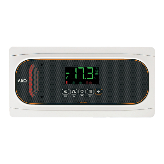
5552H4402 Ed. 01 Description SECURE 1: Visual alarm 2: Audible alarm 3: Display 4: Keypad Constant green: Trapped person pushbutton Steady: Ventilation is activated through connected. programming or forced. Quick-flashing red: Malfunction / wiring Blinking: Ventilation should be active fault in pushbutton. according to programming, but its stop has Slow-flashing red: Pushbutton not detect- been forced. -
Page 6: Installation
- Fix the device to the wall. If it is a brick wall, use the screws and plugs supplied; if the wall is made of sheet metal (cold room store), use the screws provided without plugs (6). -If installing the optional AKO-58010 battery, connect it as shown in the figure (7) - Wire the device by following the recommendations indicated on pagepage 14. -
Page 7: Wiring
The wiring to be undertaken depends on the options selected in the initial configuration wizard (See page 15). Check the enclosed schematic and the defined configuration before wiring. 100 - 240 V~ 50/60 Hz AKO-55327 extraction pushbutton Input x H.E. pushbutton AKO-55326 RS485 Remote... -
Page 8: Initial Configuration (Wizard)
5552H4402 Ed. 01 Initial configuration (wizard) The first time the unit receives the power supply, it will enter into ASSISTANT mode. The display will show the message In{ flashing at 0. The pushbuttons / detectors / transmitters / probes should SECURE SECURE be connected before initiating the process, otherwise,... -
Page 9: Operation
5552H4402 Ed. 01 Operation Messages Probe 1 faulty Gas alarm active. (Open circuit, crossed circuit or temper- ature outside the limits of the probe). Trapped person alarm active. Maximum temperature alarm in probe 1. The temperature value programmed in A1 has been reached. Open door alarm active. - Page 10 Controlled by relay RY1, it automatically activates and deactivates according to the programmed times in parameters U1 and U2 (Scheduled ventilation cycle). If necessary, its activation or stop can be forced by pressing the AKO-55327 pushbutton (B) for more than 1 second. Gas leak detection (A) If one of the connected detectors / transmitters (A) detects a gas leak (pre-alarm or alarm), the station's visual and acoustic alarm activates, and relay RY3 (D) switches to state B, (See page 16) activating forced ventilation (RY1).
- Page 11 B (See page 16). Operation in the event of power failure In the event of a power failure, with the optional battery AKO-58010 installed, the station only maintains the func- tionality of the trapped person alarm active (InI=2).
- Page 12 5552H4402 Ed. 01 Programming the ventilation cycle Ventilation cycles allow you to establish periods during which the fans are active. The programming is defined by parameters U1 (fan OFF time) and U2 (fan ON time). If U2 is set to “0”, the pro- gramming never starts.
-
Page 13: Programming Menu
5552H4402 Ed. 01 Programming menu Use the extended programming menu to configure all of the unit’s parameters in order to adapt it to your installation requirements. Press the SET key for 6 seconds to access it. IMPORTANT: If the password function has been configured as a keypad lock (b10=2), or as an access to parameters block (b10=1), you will be requested to enter the password programmed in PAS when attempting to access either of the two functions. - Page 14 5552H4402 Ed. 01 Parameters Alarm control Description Values Min. Def. Max. A0 Ventilation for excessive temperature ºC -50.0 40.0 A1 A1 Maximum in probe 1 alarm ºC 37 99.9 A2 Minimum in probe 1 alarm ºC -50.0 -50.0 A1 A3 Start-up delay for alarms A0, A1 and A2 min.
-
Page 15: Technical Specifications
5552H4402 Ed. 01 Inputs / outputs Description Values Min. Def. Max. I00 Type of probe: 0: Not connected; 1: NTC; 2: PT1000 I01 Differential of Probe 1 ºC -5.0 0.0 5.0 Configuration of digital input 1: 0=Disabled; 1=Remote Gas Pre-Alarm; 2=Remote Gas Alarm; 3=Remote Set-Hold;... - Page 16 0.5–4.5V ............. Extendable up to 100 metres with AKO-15586H extension cable 0–10V ..............Extendable up to 100 metres with AKO-15586H extension cable *Duration in alarm status at an ambient temperature of between 25 ºC. ** The AKO-15586H extension cable has an impedance of maximum cable distance 0.0172 Ohms* mm...
- Page 17 AKO ELECTROMECÁNICA, S.A.L. Avda. Roquetes, 30-38 08812 • Sant Pere de Ribes. Barcelona • Spain www.ako.com We reserve the right to supply materials that might vary slightly to those described in our Technical Sheets. Updated information is available on our website.
Need help?
Do you have a question about the AKO-555244 and is the answer not in the manual?
Questions and answers