
Subscribe to Our Youtube Channel
Related Manuals for AKO AKO-16526AN V2


Summary of Contents for AKO AKO-16526AN V2
- Page 1 1652H6A32 Ed. 03 AKO-16526A V2 AKO-16526AN V2 Advanced temperature and electronic expansion controller for cold room store User manual...
-
Page 2: Table Of Contents
Only qualified personnel may install the product or provide technical support. This product has been developed for use in the applications described in the manual. AKO Electromecánica does not guarantee its operation in any use not foreseen in this document and accepts no liability in the case of damage of any type which may result from incorrect use, configu- ration, installation or commissioning. -
Page 3: Warnings
-From -40 °C to +20 °C, if the NTC sensor is extended to 1000 m with at least a 0.5 mm cable, the maximum deviation will be 0.25 °C (cable for sensor extension ref. AKO-15586 / AKO-15586H. Earth the cable mesh at one end only). -
Page 4: Presentation
1652H6A32 Ed. 03 Presentation The AKO-16526A / 16526AN advanced controller for cold room stores has a SELFDRIVE operating mode that automatically controls (without parametrisation) the fans and adaptively minimises defrosts to optimise the perfor- mance of the cold room store: maximising time in set point and minimising costs linked to energy consumption and wear of components. -
Page 5: Description
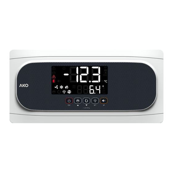
1652H6A32 Ed. 03 Description 1: Display 2: Keypad Constant: Stand-By Mode activated. Regulation Constant: The SELFDRIVE mode is active. is paused. Flashing: An error has been detected in SELF- Flashing: Controlled stop process for the regu- DRIVE mode. To view it, press the key. lation in progress. - Page 6 When an alarm is in progress, pressing once without holding mutes the acoustic alarm. Pressing for 3 seconds accesses the temperature Set Point setting. Only AKO-16526AN: Pressing the SET and ESC buttons for 3 seconds forces the trans- mission to the cloud via NBIoT connectivity.
-
Page 7: Installation
- Close the cover (3), tighten the screws (2) and replace the bezels (1). ATTENTION: When drilling the holes for the glands, take care to avoid damaging the internal com- ponents. AKO-16526AN: DO NOT DRILL ANY HOLES IN THE TOP OF THE DEVICE. - Page 8 1652H6A32 Ed. 03 Installation of the probes To achieve maximum performance from the advanced controller, correct installation of the probes is key as they are responsible for calculating the evaporator’s thermal transfer coefficient, evaluating the start and end of the defrosts and diagnosing problems in the evaporator.
-
Page 9: Initial Configuration
1652H6A32 Ed. 03 Initial configuration The AKO-16526A / AKO-16526AN controller can be adapted to different types of installation according to the different options chosen in the set-up wizard. Before completing the wiring, make sure you are familiar with the details of the installation in order to configure it correctly. -
Page 10: Assistant
1652H6A32 Ed. 03 Assistant The first time the unit receives the power supply, it will enter into ASSISTANT mode. The display will show the mes- sage In{ flashing at 0. The buttons and change the value, the SET button accepts the value and moves on to the next step. - Page 11 If the Pump Down function is active, there may be a delay between the initiation of the Stand-by function and the moment the controller stops (See page 17). Registration on akonet.cloud (only AKO-16525AN) In order for the controller to be able to send operation data to akonet.cloud, it must be registered.
-
Page 12: Operation
1652H6A32 Ed. 03 Operation Messages Pump down malfunction error (Stop). The time configured in parameter C20 has been exceeded. Only displayed on screen. Pump down malfunction error (Start). The time configured in parameter C19 has been exceeded. Only displayed on screen. Sensor 1, 2, 3, 4, 5 or 6 is faulty (open circuit, crossed circuit, or value outside sensor limits). - Page 13 1652H6A32 Ed. 03 Minimum evaporating pressure alarm. The value defined in A29 has been reached (See page 27). Activates the alarm relay and the audible alarm. Indicates that a defrost is being performed (See page 21). Only displayed on screen. Password request.
-
Page 14: Selfdrive Mode
1652H6A32 Ed. 03 SELFDRIVE mode If the SELFDRIVE mode is activated (default configuration), the device periodically evaluates the evapo- rator’s heat transfer, managing the available resources to maximise it. The defrosts are minimised, adapting to the changing conditions of the cold room, reducing heat input into the refrigerated space, thermal stress in the evaporator and energy consumption. -
Page 15: Cold Regulation
1652H6A32 Ed. 03 Cold regulation Solenoid control (COOL Relay) SP+C1 If u00=0 is selected in the wizard, coolant production is regulated by opening/closing the solenoid valve, which sends liquid to the thermostatic expansion valve. If u00=1 is selected in the wizard, coolant production is regulated by controlling the opening and Solenoid closing of the expansion valve (PWM control). - Page 16 A low superheat allows for better evaporator efficiency, but too low a value may cause liquid to enter the compres- sors because the liquid in the evaporator is not completely evaporated. The AKO-16526A / AKO-16526AN provides stable superheat regulation and a fast response to pressure or load fluctuations, thus ensuring a high level of system safety.
- Page 17 1652H6A32 Ed. 03 Pump down function This function foresees problems in the compressor caused by movements of coolant, using a stop/start technique for the installation, controlled via the liquid solenoid, the low pressure switch and the compressor itself. This function is only available for Inl 2, 5, and 7 and requires the connection of a low pressure switch in digital input 1.
- Page 18 1652H6A32 Ed. 03 Regulation of cold with two temperature probes (S1 + S3) This requires configuration of input D2/S4 as a second cold room store temperature probe (l20=10). The device regulates the temperature of the cold room store taking into account the reading of both probes. Using parameter C25, the influence of probe S3 is determined in the settings.
-
Page 19: Compressor Protection Timing
Point change (I10 or I20=4). Activation through this method cancels any other activation and can only be deactiva- ted using the same method. By means of the AKONet application. This requires the device to be connected to a Modbus network (See page 39). By means of the CAMM module and the AKO CAMM tool application. EXAMPLE: Configuration... -
Page 20: Door Management
1652H6A32 Ed. 03 Door management Standard operating mode (CE=0) Door management allows for the installation's behaviour to be controlled, should the cold room door open through parameters C22 and C23. Parameter C22 defines whether cold production should be stopped if the door opens. If C22=1, when the door opens, the fans stop and, 15 seconds later, the solenoid closes (COOL relay). -
Page 21: Defrost
1652H6A32 Ed. 03 Defrost Types of defrost There are 5 possible defrost types, depending on the option selected in the wizard (Inl): Electric (InI=1, 2 and 3) (d7=0) Defrost is performed through electrical resistors, supplying the evaporator with heat. The operation of fans in this mode depends on parameter F3;... - Page 22 1652H6A32 Ed. 03 Control of defrost in standard mode (CE=0) Max. d1 COLD REGULATION DEFROST DRIP TIME COLD REGULATION DEFROST FAN START-UP DELAY “DEF” MESSAGE SP+C1 Defrost start Defrost will start if: • The time programmed in parameter d0 has elapsed since the start of the last defrost. •...
- Page 23 1652H6A32 Ed. 03 Control of defrost in SELFDRIVE mode (CE=1) Defrosts in SELFDRIVE mode are not programmed, but rather the device evaluates the operation of the cold room and manages defrosts depending on the needs of the installation. If a drop in the performance of the cold room is detected due to formation of ice in the evaporator, defrost is activated and it is supervised until its completion.
- Page 24 1652H6A32 Ed. 03 Other defrost parameters (They have an effect in standard and SELFDRIVE mode) Drip time It is set by parameter d9 and defines the time added at the end of defrost to allow the evacuation of the remaining defrost water from the evaporator, during which time there is no cooling regulation.
-
Page 25: Management Of The Drainage Resistor
1652H6A32 Ed. 03 Other parameters Using parameter d5, you can configure whether the unit performs a defrost (d5=1) or not (d5=0) when it receives power (first start-up or after a power supply failure). Should the option YES (d5=1) be selected, defrost will begin once the delay time defined in d6 has elapsed. -
Page 26: Alarms
1652H6A32 Ed. 03 Alarms The device warns the user through an on-screen message as to activation of a relay (if a relay has been set as an alarm) and a sound alarm when the criteria programmed in the parameters are met. Maximum / minimum temperature alarm It shows the message “AK”... - Page 27 1652H6A32 Ed. 03 HACCP alarm The alarm is activated should situations be detected which could endanger the integrity of the products stored in the cold room. If the temperature of the cold room is higher than that defined in parameter h1 for a length of time exceeding that defined in parameter h2, the alarm activates, displaying the message XCP on screen.
-
Page 28: Alerts
1652H6A32 Ed. 03 Alarm delays These delays prevent certain alarms from being shown, to allow the installation to recover its normal operation after certain events. • Delays in start-up (A3): This delays the activation of the temperature alarms upon receiving power (at start- up or after a power supply failure) or when exiting Stand-by mode. -
Page 29: Light Control
1652H6A32 Ed. 03 Light control Relay AUX 1 or AUX 2 must be configured as “Light” (o00, o10 or o20=2). Switching the lights on or off is controlled using: • The push-button: One press switches the lights on or off. •... - Page 30 1652H6A32 Ed. 03 AUX 3 relay • Deactivated (o20=0): Does not carry out any function. • Alarm (o20=1): This activates the relay every time an alarm occurs (See page 26). • Light (o20=2): This regulates the operation of cold room light. •...
-
Page 31: Configuration
1652H6A32 Ed. 03 Configuration Condensed programming menu This allows for the most-used parameters to be quickly configured. Press the SET key for 3 seconds to access it. Condensed programming menu OUT OF IN PROGRAMMING PROGRAMMING 20 sec. Temperature Value Parameters indication 3 sec. -
Page 32: Extended Programming Menu
1652H6A32 Ed. 03 Extended programming menu Use the extended programming menu to configure all of the unit’s parameters in order to adapt it to your installation requirements. Press the SET key for 6 seconds to access it. IMPORTANT: If the password function has been configured as a keypad lock (b10=2), or as an access to parameters block (b10=1), you will be requested to enter the password programmed in PAS when attempting to access either of the two functions. -
Page 33: Parameters
1652H6A32 Ed. 03 Parameters Regulation and control Description Values Min. Def. Max. SP Temperature setting (Set Point) ºC/ºF -50 0.0 99 CE SELFDRIVE Mode 0=Deactivated 1= Activated C0 Sensor 1 calibration (Offset) ºC/ºF -4.0 0.0 4.0 C1 Sensor 1 differential (Hysteresis) ºC/ºF 1.0 2.0 20.0 Set point top locking... - Page 34 1652H6A32 Ed. 03 Defrost Description Values Min. Def. Max. d0 Defrost frequency (time between 2 starts) d1 Maximum defrost duration (0=defrost deactivated) min. Type of message during the defrost: 0=Sign of the real temperature; 1=Sign of the temperature at the start of the defrost; 2=Sample of the dEF message Maximum message duration min.
- Page 35 1652H6A32 Ed. 03 Expansion valve Description Values Min. Def. Max. Valve type: 1=PWM-type EEV 2=Stepper-type EEV SH Superheating set point Refrigerant gas type: 0= R-404A, 1= R-134A, 2= R-407A, 3= R-407F, 4= R-410A, 5= R-450A, 6= R-513A, 7= R-744, 8= R-449A, 9= R-290, 10= R-32, 11= R-448A, 12=R1234ze, 13=R23, 14=R717, 15=R407C, 16=R1234yf, 17=R22, 18=R454C, 19=R455A, 20=R507A, 21=R515B, 22=R452A, 23=R452B, 24=R454A u03 PWM cycle time...
- Page 36 1652H6A32 Ed. 03 Alarms Description Values Min. Def. Max. A0 Configuration of the temperature alarms 0=Relative to SP 1=Absolute A1 Alarm for maximum in sensor 1 (it must be higher than the SP) ºC/ºF A2 99.0 99.0 A2 Alarm for minimum in sensor 1 (it must be lower than the SP) ºC/ºF -50 -50 A1 Delay of temperature alarms in the start-up...
- Page 37 1652H6A32 Ed. 03 Basic configuration Description Values Min. Def. Max. b00 Delay of all functions on receiving power supply min. b01 Cold room light timing min. b10 Password function 0=Inactive 1=Block access to parameters 2=Lock keypad Password b20 MODBUS address Communication speed: 0=9600 bps 1=19200 bps 2=38400 bps 3=57600 bps b22 Audible alarm enabled 0= No 1=Yes...
- Page 38 1652H6A32 Ed. 03 Inputs and outputs Description Values Min. Def. Max. AUX1 relay configuration: 0= Deactivated, 1= Compressor/Crankcase resistan- ce, 2= Light, 3= Virtual control, 4= Alarm, 5= Door frame resistor, 6=Drainage resistor AUX2 relay configuration: 0= Deactivated, 1= Alarm, 2= Light, 3= Virtual control, 4= Defrost 2nd evaporator, 5= Door frame resistor, 6= Equal solenoid status, 7= Equal device status, 8=Drainage resistor AUX3 relay configuration: 0= Deactivated, 1= Alarms, 2= Light,...
-
Page 39: Connectivity
The controllers are equipped with a port for connection of RS485 (MODBUS) data, which allows for remote manage- ment of these using a AKO-5010, AKO-5025, AKO-5041 or AKO-5051 gateway. The MODBUS address is factory-set and is indicated on the rating plate located on the left side of the controller. This address must be different for each unit within the same network. -
Page 40: Technical Specifications
Resolution, adjustment and differential ......................0.1 ºC Thermometric accuracy ..........................±1 ºC Tolerance of the NTC probe at 25 ºC ......................±0.4 ºC Input for NTC probe ....................AKO-14950 / AKO-14950-8 Working ambient temperature .......................-10 ºC to 50 ºC Ambient storage temperature ......................-30 ºC to 60 ºC Protection degree ............................ -
Page 41: Simplified Declaration Of Conformity
1652H6A32 Ed. 03 Simplified declaration of conformity AKO Electromecánica S.A.L. hereby declares that the radioelectric device types AKO-16526AN (Advanced temperatu- re controller for cold rooms with NBIoT communication) conform to the provisions set forth by Directive 2014/53/EU. The full text of the EU conformity declaration is available at the following internet addres:... - Page 42 1652H6A32 Ed. 03...
- Page 43 1652H6A32 Ed. 03...
- Page 44 AKO ELECTROMECÁNICA, S.A.L. Avda. Roquetes, 30-38 08812 • Sant Pere de Ribes. Barcelona • Spain www.ako.com We reserve the right to supply materials slightly different to those described in our Data Sheets. Updated information in our website.
Need help?
Do you have a question about the AKO-16526AN V2 and is the answer not in the manual?
Questions and answers