Table of Contents

Related Manuals for Panasonic AK-HBU500G


Summary of Contents for Panasonic AK-HBU500G
- Page 1 Operating Instructions Buildup Unit AK-HBU500G Model No. Please carefully read this manual, and save this manual for future use. Before using this product, be sure to read “Read this first!” (pages 2 to 4) . ENGLISH W0316KT0 -PS...
-
Page 2: Read This First
Read this first! Read this first! WARNING: CAUTION • To reduce the risk of fire, do not expose this equipment to rain or moisture. RISK OF ELECTRIC SHOCK DO NOT OPEN • To reduce the risk of fire, keep this equipment away from all liquids. -
Page 3: Important Safety Instructions
EMC NOTICE FOR THE PURCHASER/USER OF THE APPARATUS 1. Applicable standards and operating environment (AK-HBU500G) The apparatus is compliant with: • standards EN55103-1 and EN55103-2, and •... - Page 4 AEEE Complies with Directive of Turkey. Note: The rating plate (serial number plate) is on the bottom of the unit. Manufactured by: Panasonic Corporation, Osaka, Japan Importer’s name and address of pursuant to EU rules: Panasonic Marketing Europe GmbH Panasonic Testing Centre...
- Page 5 Read this first! Introduction How to View This Manual About trademarks and registered trademarks Illustrations and screen displays featured in the manual Abbreviations Overview Accessories Precautions for Use Parts and their functions Front panel Top panel Bottom panel Right side panel Rear panel Operation panel 1 Operation panel 2...
-
Page 6: How To View This Manual
For the purposes of this manual, the model numbers of the units are given as listed in the table below. Model number of unit Model number given in manual AK-HC5000G AK-HC5000 AK-HC5000GS AK-UC3000G AK-UC3000 AK-UC3000GS AK-HRP1000 AK-HRP1000 AK-HRP1000G AK-HRP1005G AK-HRP1005 AK-UCU500P AK-UCU500PS AK-UCU500 AK-UCU500E AK-UCU500ES AK-MSU1000G AK-MSU1000 AK-HVF100G AK-HVF100 AK-HBU500G AK-HBU500 - 6 -... -
Page 7: Precautions For Use
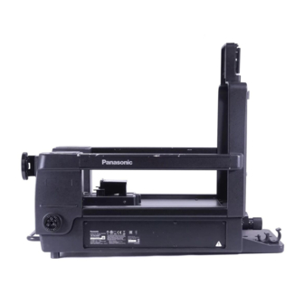
Introduction Overview This unit is a buildup unit for use with studio handy cameras (AK-UC3000, AK-HC5000). When installed in the studio handy camera, it enables a large lens to be mounted, thus yielding the same range of operations as that afforded by a larger camera. -
Page 8: Parts And Their Functions
Parts and their functions Parts and their functions Front panel Lens guide The 2/3-type large lens is attached by hooking it onto this guide. Align the guide pin of the lens with the center groove, and attach. “Mounting the large lens” (see page 15) Lens anchoring knob This is rotated clockwise to anchor the large lens. -
Page 9: Top Panel
Parts and their functions Top panel Camera mount base (rear) This is used to attach the camera. “Mounting the camera” (see page 18) Camera I/F connector This is the interface connector which is used when connecting the camera. Bottom panel Tripod screw socket This is used to attach the unit to a tripod or other accessory. -
Page 10: Right Side Panel
Parts and their functions Right side panel Clamp for optical fiber cable The optical fiber cable connected to the camera from the unit is secured to this clamp. Hook for securing cable The camera's optical fiber cable is fastened to this hook. [DC OUT 12V 7.5A] connector This is a 12 V DC output connector. -
Page 11: Rear Panel
Parts and their functions Rear panel Camera mount base (front) This is used to attach the camera. “Mounting the camera” (see page 18) Camera lock lever This is used to secure or release the camera. “Mounting the camera” (see page 18) Optical axis adjustment knob This adjusts the optical axis position in the horizontal (left and right) direction. -
Page 12: Operation Panel
Parts and their functions Operation panel 1 [POWER] lamp This lights green when the buildup unit is turned on. Flashing lamp When external DC power is being supplied via the [DC IN] connector and the [POWER] switch on the camera (AK-UC3000/AK-HC5000) is set to [EXT]: If a total current consumption level that includes the external DC output and exceeds the specifications is detected, the lamp flashes red. - Page 13 Parts and their functions [CURSOR 3] button When all the [CURSOR] buttons (1 to 3) are unlit and the [CURSOR ON/OFF] button is set to ON, you can press and hold the [CURSOR 3] button for about 2 seconds to store the current cursor state to memory.
- Page 14 Parts and their functions Operation panel 2 11 12 [ND (1, 2, 3, 4, 5)] indic- These indicate the positions of the ND filter. 2 lights green, and 1, 3, 4, and 5 light orange. ator [ND] dial This is used to select the ND filter position. It is effective when the [LOCAL] button is held down.
- Page 15 Mounting Mounting Mounting the large lens A. Lens B. Pin C. U-shaped groove D. Connectors E. Lens clamp lever F. Lens anchoring knob The procedure 1. Loosen the lens anchoring knob (F) (1), and push down the lens clamp lever (E) to the left side (2). 2.
- Page 16 Mounting Mounting the buildup unit on a tripod An illustration of the lens has been omitted. A. Grip B. Rear handle C. V-edge D. Tripod E. Bottom panel of buildup unit The procedure 1. Attach the V-edge (C) supplied with the tripod to the tripod mounting area on the bottom panel of the buildup unit (E) using the two screws.
-
Page 17: Preparing The Camera
Mounting Preparing the camera A. Camera hangers x 2 (supplied with camera) B. Lens clamp lever C. Shutter switch cover D. Viewfinder front/back anchoring lever E. Viewfinder mount The procedure 1. Remove the portable lens mounted on the camera or the mount cap supplied with the camera. 2. -
Page 18: Mounting The Camera
Mounting Mounting the camera The instructions for mounting the camera given here are for when a large lens is not mounted on the buildup unit. The procedure is the same even when a large lens has already been mounted. NOTE Before mounting the camera, turn off the power of the camera without fail. - Page 19 Mounting 3. Push up the camera lock lever (A) to secure the camera. NOTE The camera will not be securely locked if the camera lock lever is not pushed up all the way. Camera lock lever - 19 -...
- Page 20 Mounting Optical axis adjustments Display an image, and if the camera’s optical axis is out of alignment (if the center of the image is different at the telephoto and wide-angle ends as a result of zooming the lens), the optical axis position can be adjusted by following the steps below. The procedure 1.
- Page 21 Mounting 3. Turn the optical axis adjustment knob (L/R) (C) in the R direction to align the horizontal optical axis pos- ition. Optical axis adjustment knob (L/R) NOTE Always perform the procedure in the proper order (1→2→3). There is backlash (unsteadiness in operation) in the optical axis adjustment knobs that can make alignment of the optical axis position difficult, unless you adjust from a single dir- ection at a time.
-
Page 22: Detaching The Camera
Mounting Detaching the camera The instructions for detaching the camera given here are for when a large lens is not mounted on the buildup unit. The procedure is the same even when a large lens has already been mounted. NOTE If the buildup unit is mounted on a tripod, secure the pan lock lever and tilt lock lever of the tripod. -
Page 23: Assigning Functions To User Buttons
Adjustments Adjustments Adjusting the light-emitting components Each light-emitting component can be adjusted from the connected camera. Refer to [MANTENANCE] > [BUILDUP LIGHT ADJUST] of the camera's menu. BUILDUP LIGHT ADJUST Setting item Corresponding light-emitting component BOX SW (PUSH SW) [USER1 (LENS EXT)] button [USER2 (CENTER)] button [USER3] button [RET A] button... - Page 24 Connection Connection Connect the camera (and lens) and the buildup unit as shown in the figure below. 8˝ LCD Viewfinder AK-HVF100 Studio Handy Camera AK-UC3000 Master Setup Unit AK-HC5000 AK-MSU1000 (Available soon.) Camera Control Unit AK-UCU500 Large lens Buildup Unit AK-HBU500 External DC power Remote Operation Panel...
-
Page 25: Troubleshooting
Troubleshooting Troubleshooting Symptom Cause and Measure The power indicator LED [POWER] does not light. Check whether the camera has been mounted properly on the buildup unit. (No power is supplied to the buildup unit.) Try turning off the power of the camera and then turning it back on. A large lens cannot be mounted. -
Page 26: Connector Pin Assignment Table
Reference Reference Connector pin assignment table CAMERA I/F connector QR/P8-20P-C(01) by Hirose Electric 1 2 3 4 5 6 7 8 9 13 14 15 16 17 18 19 Pin No. Signal VF PB OUT GND VF PB OUT VF PR OUT GND VF PR OUT VF Y OUT VF Y OUT GND... -
Page 27: Lens I/F Connector
Reference LENS I/F connector 57-20360 made by DDK Pin No. Signal UNREG +12 V UNREG_GND AGND FGND EXT_MODE_A/S_IN EXT MODE_B EXT MODE_C 16:9/4:3 SEL IRIS_POSI ZOOM_POSI RET1 RET2 FOCUS_POSI IRIS_CONT IRIS_A/R/S_OUT PROJECTOR_ON 2*LIGHT_ON TALLY_CONT RET3 LENS_CODE_A LENS_CODE_B LENS_CODE_C LENS_CODE_D EXT_CONT_A EXT_CONT_B INCOM1_ENG/PD INCOM2_ENG/PD... - Page 28 Reference DC IN connector HA16RA-4P (77) by Hirose Electric Pin No. Signal UNREG GND +12 V DC OUT 12V 1.5A connector HR10A-7R-4SB by Hirose Electric Pin No. Signal UNREG +12 V - 28 -...
- Page 29 Reference DC OUT 12V 7.5A connector HA16PRK-4S by Hirose Electric Pin No. Signal UNREG +12 V - 29 -...
- Page 30 Reference Appearance Unit: mm (inch) 300(11-13/16) 510(20-1/16) - 30 -...
-
Page 31: Specifications
Specifications Specifications Power input 12 V DC ( ) (when external power is supplied) Power supply 240 V AC ( ) 50/60 Hz (when AK-UCU500 is connected) 70 W (when external power is supplied) Power consumption 165 W (when AK-UCU500 is connected) indicates safety information. - Page 32 Index Index Mounting Adjustments ND (1, 2, 3, 4, 5) indicator BOX/CROSS button ND dial CALL button Optical axis adjustment knob (L/R) Camera Optical axis adjustment knobs (UP/DOWN) Detaching Optical axis adjustments Mounting Camera height screw POWER lamp Camera I/F connector Preparing Camera lock lever Camera mount base (front)
- Page 33 MEMO - 33 -...
- Page 34 Web Site: http://www.panasonic.com © Panasonic Corporation 2016...
Need help?
Do you have a question about the AK-HBU500G and is the answer not in the manual?
Questions and answers