Table of Contents
Advertisement
Quick Links
Advertisement
Table of Contents

Related Manuals for Honeywell HON-AOR-16


Summary of Contents for Honeywell HON-AOR-16
- Page 1 AREA OF REFUGE USER MANUAL AND INSTALLATION GUIDE Read and save these instructions before installation and use _______________________ Model number(s) HON-AOR-16 HON-AOR-16-R ______________________________ www.honeywellareaofrefuge.com 771-00007 aorsupport@talkaphone.com Rev 1.0 | 06/12/2024...
- Page 2 Find out more at www.talkaphone.com. The Honeywell trademark is used under license from Honeywell International Inc. Honeywell International Inc. makes no representation or warranties with respect to these products. These products are manufactured by Talk-A-Phone, LLC, Niles, IL 60714, USA.
-
Page 3: Table Of Contents
Table of contents ........................... 4 BOUT THIS GUIDE ONTENTS ........................7 ECHNICAL EQUIREMENTS ..........................10 YSTEM VERVIEW – HON-AOR-16* ..................... 11 RONT PERATING ANEL – HON-AOR-16* ....................12 NTERNAL OMPONENTS NSTALLATION ......................... 23 YSTEM ROGRAMMING ........................31 PERATING NSTRUCTIONS ............................ 33... -
Page 4: About This Guide
Date Description • Software Releases June 12, 2024 Initial release of HON-AOR-16*. TPAORC V1.6 Intended audience This guide is primarily intended for field personnel who install and configure the product. Related documents The following list identifies publications that may contain information relevant to the information in this document: •... -
Page 5: Contents
CONTENTS Contents Please ensure receipt of each of the included HON-AOR-16 Command Unit components: Part Number Description HON-AOR-16* 16-Station Area of Refuge Command Unit 68430 Siren/strobe 68684 12VDC, 5Ah Backup Battery *-R provides a red enclosure instead of black DocID ((771-00007)) - Page 6 CONTENTS Accessory components (sold separately) include: Part Number Description HON-AOR-TR16 Flush mount trim ring for HON-AOR-16 Command Unit. Unit is painted black. HON-AOR-TR16-R Flush mount trim ring for HON-AOR-16-R Command Unit. Unit is painted red. 42970 6-18 Phillips Screw for Flush Mount Trim Ring (for replacement).
-
Page 7: Technical Requirements
Programming At time of installation or programming, please have a telephone test set ready—while DTMF programming commands can be issued from the built-in local phone of the HON-AOR-16 Command Unit, the telephone test set will be helpful in some cases. - Page 8 Not compatible with the HON-AOR-16 Command Unit Power for HON-AOR-CS Analog Call Stations HON-AOR-CS Analog Call Stations are line-powered by the HON-AOR-16 Command Unit. When connected to the Command Unit, the line must provide a minimum of 24V at 20 mA off-hook (no current is drawn on-hook).
- Page 9 TECHNICAL REQUIREMENTS PSTN/POTS Telephone Line For Local Mode Only: No external phone line (i.e. POTS/PSTN telephone line) or cellular gateway is required if the on- premise answering point is constantly attended. For Remote Mode: Two (2) dedicated POTS/PSTN telephone lines (i.e. analog telephone line or analog PBX extension line).
-
Page 10: System Overview
When a HON-AOR-CS Analog Call Station calls and the HON-AOR-16 Command Unit is in Mixed Mode, it will ring the built-in local phone of the HON-AOR-16 Command Unit first, ring it a second time if no one answers the first time, then if no one answers the second time it will dial a remote number. If no... -
Page 11: Front Operating Panel - Hon-Aor-16
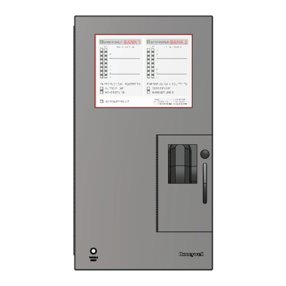
FRONT OPERATING PANEL – HON-AOR-16* Front Operating Panel – HON-AOR-16* Item Component Label for BANK Number LEDs for Call Status of Call Stations LEDs for Call Station Cabling Faults (Opens/Shorts) Physical Location Labeling for Call Stations LEDs for Telephone Line and Local Phone Status... -
Page 12: Internal Components - Hon-Aor-16
INTERNAL COMPONENTS – HON-AOR-16* Internal Components – HON-AOR-16* Item Component 8-channel Controller Board, Qty. (2), Stacked Local Phone Local Phone Bank Selector Buttons TELCO IN Terminals, Qty. (2) Backup Batteries, Qty. (2) Internal Power Supply Relays for Open/Short/System Ground Fault, Qty. -
Page 13: Installation
7. Flush Mounting into an Interior Wall: The HON-AOR-16 Command Unit has six (6) screw points on the sides which can be used to mount the Command Unit within a wall. Both halves of the HON-AOR-TR16 / HON-AOR-TR16-R trim ring should be secured to the wall using the provided 6-18 screws. - Page 14 INSTALLATION 8. Interfaces for HON-AOR-16* Controller Board This section outlines the interfaces on the HON-AOR-16* controller board. The HON- AOR-16 Command Unit contains two (2) of these controller boards. CONFIG – This push button is used to configure fault detection for the HON-AOR-CS Analog Call Stations (A) STATION 1 –...
- Page 15 Black, Red, and Orange lead wires from the controller boards in the internal compartment of the HON-AOR-16 Command Unit. The Black wire is a common negative and needs to be connected to both the strobe and siren negative terminals.
- Page 16 FACP. These wires should originate from the set of relay blocks located in the upper-left area boxed in red as illustrated here: Figure 4. Open/short/system ground fault relay block, QTY (2), on the HON-AOR-16 Command Unit. DocID ((771-00007))
- Page 17 These wires should originate from the terminal block on the upper-left of the controller board—see area boxed in red as illustrated below: 12. The HON-AOR-16 Command Unit can support up to sixteen (16) HON-AOR-CS Analog Call Stations divided into two (2) banks of eight (8).
- Page 18 INSTALLATION 14. Terminating HON-AOR-CS Analog Call Station Cabling: Terminate the cabling for each HON-AOR-CS Analog Call Station to Ports 1 through 8 (see below illustration) of the appropriate controller board (i.e. bank). The tip and ring connections for the HON-AOR-CS Analog Call Stations are NOT polarity sensitive. Ports 1-8 for HON-AOR-CS Analog Call Stations...
- Page 19 TELCO IN terminals for each respective bank—this connection is NOT polarity sensitive (see below). The TELCO IN terminals are located on the left side of the HON-AOR-16 Command Unit chassis— just above the backup batteries.
- Page 20 INSTALLATION 16. Connecting Primary Power: Once the appropriate low voltage field cabling terminations have been completed, connect the primary power (See, Power for Command Unit (p.6), for primary power requirements) to the internal power supply located in the lower-left of the Command Unit internal compartment. The LINE and NEUTRAL leads are located on the lower-left side of the internal power supply (see photo below).
- Page 21 INSTALLATION 17. Connecting Backup Batteries: Install the backup batteries and connect them to the power supply board by inserting the connector onto the header pins located on the bottom right of the internal power supply. Match and connect the cables marked “3” through “6” to the corresponding terminals marked “3”...
- Page 22 INSTALLATION 18. Fault Detection Configuration for HON-AOR-CS Analog Call Stations: Carrying out this procedure on the controller board is required for proper open/short fault detection on the system. In the upper-right of each controller board (i.e. bank), there is an orange-red configuration button located to the left of Ports 1-4.
-
Page 23: System Programming
SYSTEM PROGRAMMING System Programming List of Programming Codes for the Command Unit Command Function * 31 * [up to 8 digits] * Guard Access Code entry for phone programming [Default * 31 * *] Master Access Code entry to change Guard Access Code or Master Access Code * 30 * [up to 8 digits] * [Default * 30 * 12345678 *] Resets controller board programming to factory defaults. - Page 24 SYSTEM PROGRAMMING Programming the Command Unit 1. Each controller board (i.e. bank) of the HON-AOR-16 Command Unit is programmed individually. There are two (2) methods to program each controller board of the Command Unit: • At the HON-AOR-16 Command Unit via the keypad of the built-in local phone;...
- Page 25 SYSTEM PROGRAMMING 5. Mixed Mode: The HON-AOR-16 Command Unit has two (2) controller boards—you will need to repeat this programming procedure for the second bank or controller board. a. Pick up the local phone handset and press the button corresponding to the bank of phones (i.e.
- Page 26 SYSTEM PROGRAMMING Programming the HON-AOR-CS Analog Call Stations Once the HON-AOR-16 Command Unit has been programmed, the HON-AOR-CS Analog Call Stations will need to be programmed individually. For the HON-AOR-16 Command Unit, there are two (2) controller boards—you will need to repeat the programming procedure for the HON-AOR-CS Analog Call ATTENTION Stations connected to the second controller board.
- Page 27 SYSTEM PROGRAMMING 4. Program the Second Phone Number to dial: [0-20 digits for phone number] # 01 Follow the same dialing rules as outlined in Step (3). 5. Set the call length, silence time out, ring count, and dial next number on busy: 294521 # 18 See, Timing/Dialing Options for the HON-AOR-CS Analog Call Station...
- Page 28 SYSTEM PROGRAMMING List of Programming Codes for the HON-AOR-CS Analog Call Station Command Memory Slot Function 0-20 digits Primary autodial phone number 0-20 digits Secondary autodial phone number 0-20 digits Third autodial phone number 0-20 digits Fourth autodial phone number 0-20 digits Fifth autodial phone number Timing/dialing options.
- Page 29 SYSTEM PROGRAMMING Timing/Dialing Options for the HON-AOR-CS Analog Call Station The timing/dialing option code is comprised of six (6) digits defined in the table below. Parameter Function Values Definition 0.1 seconds 0.2 seconds [Default] 0.3 seconds Talk/Listen Delay. 0.4 seconds Switching time between talk and listen modes (i.e.
- Page 30 SYSTEM PROGRAMMING (Continued) Timing/Dialing Options for the HON-AOR-CS Analog Call Station Parameter Function Values Definition Disabled 10 seconds 20 seconds 30 seconds Silence Time Out. Sets 40 seconds the length of time a call [Default] will be connected without any voice 50 seconds transmission.
-
Page 31: Operating Instructions
(microphone and speaker are active). Answering Calls at the Command Unit 1. When calls are routed to the local phone at the HON-AOR-16 Command Unit, the local phone will ring and the siren/strobe will activate. 2. To answer the call, pick up the local phone handset and press the appropriate bank button (“BANK 1”... - Page 32 OPERATING INSTRUCTIONS Answering Calls Off-site or at a Central Station When calls are routed off-site (i.e. monitoring service, call center, central station, or 911), calls are answered accordingly and a prerecorded voice message with physical location information may play at the beginning of the call.
-
Page 33: System Faults
(every 24 hours) if the fault is still present. Primary Power Loss When the HON-AOR-16 Command Unit loses primary power and begins to run on battery backup, the AC POWER FAULT LED will solidly illuminate on the Command Unit panel. -
Page 34: System Maintenance
SYSTEM MAINTENANCE System Maintenance NFPA 72 requires that area of refuge two-way communication systems be inspected, tested, and maintained on an annual basis. NFPA 72 specifies the method required as “verify location and condition”. As such, the following guidelines are highly recommended: •... -
Page 35: Frequently Asked Questions
Frequently Asked Questions 1. Can the system support more than one (1) local answering point? No, the HON-AOR-16 Command Unit does not currently support additional local answering points. 2. Can each controller board (i.e. bank) share a single PSTN/POTS telephone line or single cellular... -
Page 36: General Troubleshooting
GENERAL TROUBLESHOOTING General Troubleshooting Problem Possible Causes The Command Unit does 1. The internal power supply is not properly connected (check primary not function at all. It cannot power and the backup batteries). dial out or it cannot be 2. The cabling for the PSTN/POTS telephone lines, analog PBX extension called into. -
Page 37: Servicing
SERVICING Servicing For product service and repair, please contact: Talkaphone Area of Refuge (AOR) Support Email: aorsupport@talkaphone.com Phone: 773.539.1100 DocID ((771-00007)) -
Page 38: Limited Warranty Information
LIMITED WARRANTY INFORMATION Limited Warranty Information For the latest warranty information, please visit: https://www.honeywellareaofrefuge.com/warranty DocID ((771-00007)) -
Page 39: System Installation Information Sheet
SYSTEM INSTALLATION INFORMATION SHEET System Installation Information Sheet IMPORTANT NOTE: This installation information sheet has been provided in order to record and safely retain information for future maintenance and operation of this Area of Refuge system. Area of Refuge System Installation Address: Installation Date: To reach this Command Unit, call this(these) phone number(s):... -
Page 40: Operating Instruction Sheet For The Command Unit
OPERATING INSTRUCTION SHEET FOR THE COMMAND UNIT Operating Instruction Sheet for the Command Unit This sheet must be completed, framed, and placed adjacent to the Command Unit for ready reference. Area of Refuge System Model Number: HON-AOR-16 Issue Date: OPERATING INSTRUCTIONS: ANSWERING A CALL An initial call will RING the local phone handset. -
Page 41: Fault Conditions And Service Contact Instruction Sheet
IMPORTANT NOTE: The below fault conditions and service contact instruction sheet must be completed and then framed and placed adjacent to the Command Unit for ready reference. Area of Refuge System Model Number: HON-AOR-16 Issue Date: FAULT CONDITIONS: • TEMPORARILY SILENCING THE AUDIBLE FAULT ALARM – USE THE TROUBLE RESET BUTTON. - Page 42 Niles, IL 60714 The Honeywell trademark is used under license from Honeywell International Inc. 773.539.1100 Honeywell International Inc. makes no representation or warranties with respect to these products. These products are manufactured by Talk-A-Phone, LLC, Niles, IL 60714, USA. aorsupport@talkaphone.com www.honeywellareaofrefuge.com...
Need help?
Do you have a question about the HON-AOR-16 and is the answer not in the manual?
Questions and answers