Honeywell HZ432 TrueZONE Installation Manual
Zone panel professional
Hide thumbs
Also See for HZ432 TrueZONE:
- Installation manual (24 pages) ,
- User manual (4 pages) ,
- Installing manual (2 pages)
Advertisement
Advertisement
Table of Contents

Related Manuals for Honeywell HZ432 TrueZONE


Summary of Contents for Honeywell HZ432 TrueZONE
- Page 1 HZ432 TrueZONE Zone Panel Professional Installation Guide 69-2198-01...
-
Page 2: Table Of Contents
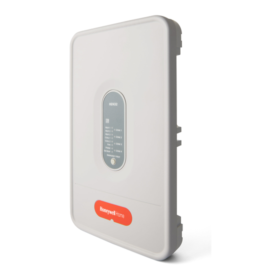
Emissions: Complies with FCC Class B, part 15 requirements. 8 (203) 1.86 (47) M24797 Fig. 1. HZ432 TrueZONE panel dimensions in in. (mm). Need Help? For assistance with this product please visit http://yourhome.honeywell.com or call Honeywell Zoning Hotline toll-free at 1-800-828-8367 Read and save these instructions. -
Page 3: Accessories
HZ432 TrueZONE aCCEssOriEs Table 1. Recommended Thermostats. Table 3. Maximum Dampers.* System Non- Programmable Ambient Temp. Maximum Damper VA per Zone Programmable 100°F (38°C) 28.8 Single- TH5110D, TH3110D, TH8110U, TH6110D, 160°F (71°C) 16.8 Stage T87N TH4110D * Use an SDCR (Slave Damper Control Relay) for addi-... -
Page 4: Mounting
SPRD BYPASS ZD SERIES equipment; locate it on a wall, stud, roof truss, or cold- DAMPER ZONE DAMPERS air return. NOTE: The HZ432 TrueZONE panel can be mounted in any orientation; level it for appearance only. SUPPLY DATS DUCT (ALTERNATE... -
Page 5: Wiring
W1/E M24808 Fig. 4 The HZ432 offers many innovations for wire management and organization: wires can be run behind the panel, through wire channels on its sides, and must be attached to a wiring anchor with a cable tie. M24743 Fig. - Page 6 Installation Guide WiriNg DATS Connect DATS as shown. DATS M24804 C7735A1000 Fig. 7 Connect outdoor air temperature sensor as shown. Required for dual fuel systems; C7089U1006 optional for other multistage systems. OUTDOOR TEMPERATURE M28207 SENSOR Fig. 8 Connect equipment as shown. The DS/BK terminal is used with a variable-speed fan.
- Page 7 HZ432 TrueZONE CONvENTiONal The following diagram is an overall view of wiring for a conventional system as depicted in steps 3–9. ARD OR ZD DAMPER SPRING-OPEN POWER-CLOSED RRD OR MARD DAMPER M1 COMMON POWER-OPEN POWER-CLOSED M4 OPEN M6 CLOSED W1/E...
-
Page 8: Heat Pump
W1/E W1/E HANDLER 24 VOLT TRANS. EM. HEAT ARD OR ZD DAMPER AUX. HEAT SPRING-OPEN POWER-CLOSED W1/E FAN RELAY W1/E HZ432 HEAT PUMP (HOT) DS/BK HEAT 1 ZONE 1 HEAT 2 DEDICATED HEAT 3 ZONE 2 REVERSING COOL 1 ARD OR ZD DAMPER... - Page 9 HZ432 TrueZONE HEaT puMp Use the following diagram for wiring a 3-heat/2-cool heat pump with electric stage 3 heat. ARD OR ZD DAMPER SPRING-OPEN POWER-CLOSED RRD OR MARD DAMPER M1 COMMON POWER-OPEN M4 OPEN POWER-CLOSED M6 CLOSED W1/E W1/E HANDLER 24 VOLT TRANS.
-
Page 10: Dual Fuel
POWER-CLOSED M6 CLOSED W1/E W1/E FURNACE 24 VOLT TRANS. ARD OR ZD DAMPER SPRING-OPEN W1/E POWER-CLOSED FAN RELAY W1/E HZ432 HEAT PUMP (HOT) DS/BK ARD OR ZD DAMPER SPRING-OPEN HEAT 1 ZONE 1 HEAT 2 DEDICATED POWER-CLOSED HEAT 3 REVERSING... - Page 11 HZ432 TrueZONE Dual fuEl Use the following diagram for wiring a dual-fuel system with two-stage furnace and two-stage heat pump. ARD OR ZD DAMPER SPRING-OPEN POWER-CLOSED RRD OR MARD DAMPER M1 COMMON POWER-OPEN POWER-CLOSED M4 OPEN M6 CLOSED W1/E W1/E FURNACE 24 VOLT TRANS.
-
Page 12: Basic Configuration
Adjust settings up or down by pressing the Adjust Setting button. The flow chart below illustrates basic zone panel configuration. For additional configuration, see Advanced Configuration on page 12. The label on the inside cover of the HZ432 Zone Panel also con- tains configuration information. Fig. 18... - Page 13 HZ432 TrueZONE CONNECT WirElEss DEviCEs WIRELESS HOME CONFIG CHECK OUT MODE Press the Mode button until the Wireless LED lights up. The TrueZONE must be configured for wireless devices to select Wireless mode. BACK ADJUST SETTING NEXT M28194 Press Next to add devices.
-
Page 14: Advanced Configuration
Installation Guide aDvaNCED CONfiguraTiON Use the Adjust Setting, Next, and Back buttons to configure the zone panel. See the Configuration section on page 10 for instructions on using these buttons. Table 5. Advanced Configuration. Menu Name Menu Title (LCD Menu Options (LCD bottom Menu option description Notes: top line) -
Page 15: Operation
The LEDs indicate the following information. Much of this information, as well as configuration information, is listed on the label on the inside of the HZ432 cover. For users who prefer French or Spanish labels, HZ432 they are provided in form 69-2198FS. Cut them out and attach them to the inside of the HZ432 cover. -
Page 16: Warranty
WarraNTy Honeywell warrants the products in this catalog (except those parts designated on Honeywell’s price lists as not covered by this warranty) to be free from defects due to workmanship or materials, under normal use and service, for the following warranty periods. Honeywell VisionPRO®, Commercial VisionPRO , FocusPRO®, PRO...
Need help?
Do you have a question about the HZ432 TrueZONE and is the answer not in the manual?
Questions and answers