Table of Contents
Advertisement
Quick Links
Advertisement
Table of Contents

Related Manuals for KTI KH-9M


Summary of Contents for KTI KH-9M
- Page 1 Installation Guide 10Base-T Ethernet Hub Model: KH-9M DOC.9601311-KH9M...
- Page 2 The information contained in this document is subject to change without prior notice. Copyright Ó KTI. All Rights Reserved. TRADEMARKS Ethernet is a registered trademark of Xerox Corp. NetWare is a registered trademark of Novell Inc. WARNING: This equipment has been tested and found to comply with the limits for a Class A digital device, pursuant to Part 15 of the FCC Rules.
-
Page 3: Table Of Contents
Table of Contents Chapter 1 Introduction Introduction ................1 Features ..................2 Chapter 2 Installation Installation ................. 3 Checking AC Power ..............3 Chapter 3 Making Network Connection Network Connectors ..............4 Connecting to an Ethernet Node ..........5 Connecting to a Thin Ethernet Cable ......... 6 Hub to Hub Connection via UTP Cable ........ -
Page 4: Chapter 1 Introduction Introduction
1. Introduction Introduction This hub is an Ethernet Hub designed for the 10Base-T envi- ronment. In terms of topology, twisted-pair Ethernet 10Base-T is defined as a star topology rather than a bus. Each port on the hub connects to only one 10Base-T device via unshielded twisted-pair (UTP) cable. -
Page 5: Features
Features • Network ports: 8 UTP ports 1 BNC port (Thin Ethernet port) • Standard: UTP ports conform to IEEE 802.3 10Base-T std. BNC port conforms to IEEE 802.3 10Base2 std. • Provides an additional RJ-45 jack labeled “8C” on the UTP Port #8 for connecting to another hub in expanding the network. -
Page 6: Chapter 2 Installation Installation
2. Installation Installation You can place the hub in an area that meets the following speci- fications: Temperature:5 to 40 C when operating Humidity: 10% to 80% when operating Dimension: 195 mm x 129 mm x 28 mm (WxDxH) Checking AC Power One AC power adapter is contained in the hub package. -
Page 7: Chapter 3 Making Network Connection
3. Making Network Connections Network Connectors The hub has 8 UTP ports and one BNC connector. The UTP ports are presented by 8 RJ-45 jacks. The jacks labeled 1 through 8 are permanently configured as IN jacks and the jack labeled “8C”... -
Page 8: Connecting To An Ethernet Node
Connecting to an Ethernet Node To connect the hub to a 10Base-T Ethernet node, follow these steps: 1. Select an appropriate length of 10Base-T UTP cable for the connection. 2. Connect one end of the UTP cable to the OUT jack on the device (e.g., a PC equipped with 10Base-T Ethernet adapter). -
Page 9: Connecting To A Thin Ethernet Cable
connectors to the hub. Refer to Appendix “RJ-45 Jack Pin As- signments” for the information of UTP wire pairs. Connecting to a Thin Ethernet Cable To connect the hub to a Thin Ethernet cable, follow these steps: 1. A BNC T-connector should be installed on the trunk segment cable so that the hub can be connected to the thin Ethernet cable. -
Page 10: Hub To Hub Connection Via Utp Cable
Enable the embedded 50-ohm cable terminator Disable the embedded 50-ohm cable terminator Hub to Hub Connection via UTP Cable When the number of 10Base-T nodes in your network exceeds eight, you need to connect at least two hubs to integrate all 10Base-T nodes into one network. - Page 11 The maximum length of the UTP cable connecting two hubs is 100 meters. When connecting more than two hubs via UTP ports and UTP cables, it is important to minimize the number of hubs in any path of the network. You may select one hub to serve as a primary hub to which other hubs will be connected.
-
Page 12: Hub To Hub Connection Via Thin Cable
Hub to Hub Connection via Thin Cable Another way to connect more than one hub is using a Thin Ethernet cable as a trunk cable. All hubs connect to the cable as shown in the following figure:... - Page 13 Standard Ethernet Connection Rules According to the IEEE 802.3 Ethernet standard, there are two important rules that must be followed whenever installing a hub in an Ethernet network. 1. There must be no more than five segments between any two nodes. The segment can be 10Base-T UTP cable, Thin coaxial Ethernet cable, or Thick cable.
-
Page 14: Chapter 4 Interpreting Hub Leds Locations Of The Hub Led Indicators
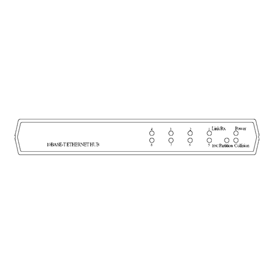
4. Interpreting Hub LEDs Locations of the Hub LED Indicators The hub provides the following LEDs : . one Power status LED . one Collision status LED . eight Link and activity status LEDs. One for each UTP port . one Partition LED for the BNC port Power LED The LED indicates the status of the hub’s power source. -
Page 15: Interpretation
Link/Rx LED Each UTP port has one Link/Rx LED to indicate the link sta- tus and receiving activities of the connection to the attached device. State Indication Interpretation Normal the UTP link is in good condition and no receiving activities are present. Blink Normal the UTP link is in good condition and there receiving activies are present. -
Page 16: Appendix Specifications
Appendix Specifications Temperature: Operating 5 to 40 Storage to 70 Humidity: Operating 10% to 80% Storage 5% to 90% Dimension: 195mm (W) x 129mm (D) x 28mm (H) 7.7 inch (W) x 5.1 inch (D) x 1.1 inch (H) RJ-45 Jack Pin Assignments The following illustrations indicate the pin assignments of the RJ-45 jacks on the hub. -
Page 17: Utp Cabling Requirements
UTP Cabling Requirements The hub’s UTP ports support standard 10Base-T cable topolo- gies and types, including Category 3, 4, or 5 unshielded twisted pair cable. The cable, quality, distance, and connectors must comply with the EIA/TIA 568 “Commercial Building Wiring Standard”. The maximum length supported by the Ethernet is 100 meters of UTP cable.
Need help?
Do you have a question about the KH-9M and is the answer not in the manual?
Questions and answers