Advertisement
User's Manual
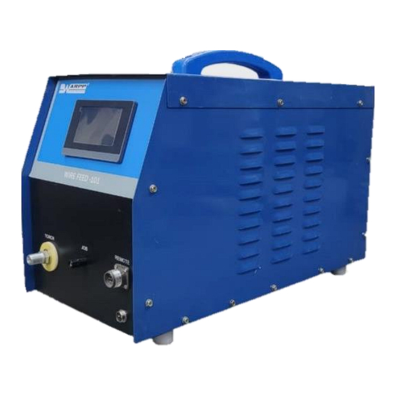
WIRE FEED- 101
WARPP ENGINEERS PVT.LTD.
Survey No. 36, House No. 15/3, Unique Industrial Estate
Dhumal Nagar Vasai (East) Distt. Palghar (Maharashtra)
INDIA – PIN -401208
Tel: 8551817744 / 8551819944 / 8551817868 - 69 / 8551812002
Customer Care Tel: 8080808734
Email:
-service@warpp.co.in
Website: -www.warpp.co.in
1
Advertisement
Table of Contents

Related Manuals for WARPP WIRE FEED-101


Summary of Contents for WARPP WIRE FEED-101
- Page 1 User’s Manual WIRE FEED- 101 WARPP ENGINEERS PVT.LTD. Survey No. 36, House No. 15/3, Unique Industrial Estate Dhumal Nagar Vasai (East) Distt. Palghar (Maharashtra) INDIA – PIN -401208 Tel: 8551817744 / 8551819944 / 8551817868 - 69 / 8551812002 Customer Care Tel: 8080808734 Email: -service@warpp.co.in...
- Page 2 The machine has been carefully inspected both mechanically and electrically before it left the factory. The machine should be initially inspected upon receipt, if any damage which may have occurred in transit inform “WARPP ENGINEERS PVT.LTD”. Or it’s Dealer immediately. Check for the accessories supplied against those listed in packing slip.
- Page 3 INDEX 1. Safety Precautions 2. Product Features 3. Technical Specification 4. Working Flow 5. Installation 6. Controls 7. Parameters & its operational meaning 8. How to operate the machine 9. Trouble Shooting 10. Wiring Diagram Maintenance Spare Part List...
- Page 4 1. Safety Precautions General safety precaution: Please strictly comply with the rules defined in this manual to avoid unexpected accidents. How to connect to power supply, select working area, please comply with proper rules Not allow non-operator to enter working area. ...
- Page 5 Don’t weld in the flammable gas or weld container which contains flammable material, otherwise it can cause explosion. Don’t weld encapsulated containers, otherwise it can cause break. Ensuring a fire extinguisher at hand in case fire break out. Avoid being hurt by moving parts: ...
- Page 6 2. Product Features 1) Digital Software controller-based design. 2) Saves all the set parameters in the software controller. 3) Compact and lightweight design. 4) Stepper motor-based design for accurate feeding. 5) User-friendly screen for better readability and settings. 6) Pulse mode with settable ON and OFF Time. 7) Settable filler wire feed ON delay.
- Page 7 3. Technical Specification Parameters Description WIRE FEED- 101 Main I/P Power Supply 230Vac ±10% / 50Hz A) 4 Ampere. B) 1.8-degree bipolar stepper motor. Stepper Motor specification C) Max DC supply to the bipolar stepper motor 48 VDC. Weight 22Kg Dimension(L*W*H) (580×285×420) mm.
-
Page 8: Digital Display
4. Working Flow Block Diagram: DIGITAL DISPLAY AC INPUT SMPS SOFTWARE CONTROLLER MOTOR DRIVE In this machine first I/P AC supply is given to the SMPS and then SMPS converted this voltage into the 24VDC output voltage. This output voltage is apply to the software controller, Digital display screen and also to the motor drive for operation. - Page 9 5. Installation 1) Place the machine in the room where there is no straight sunlight, no rain, less dust, low humidity and temperature range of 0° - 50°C. 2) The gradient of ground must not be more than 15°. 3) Connect Input supply to the machine. Supply voltage must be in the range of 230V ±...
- Page 10 1) The wire feed 101 can only be interfaced with the Warpp brand welding power source. It cannot be interfaced with other welding machines. 2) The Trigger of the Warpp welding power source and the trigger of the wire feed 101 can be controlled by a torch switch.
- Page 11 6. Controls Front panel Details: 1) Display Screen: to display the parameters and we put the parameters as per requirements. 2) Remote: This is a socket for Control lead. it is optional accessories. 3) 2 Pin Connector: This is a for trigger as shown in interfacing diagram. 4) Job: This is connected to welding job earth.
- Page 12 Back Panel : 1) Input AC Supply cable. 2) Fuse holder with Fuse. 3) ON/OFF switch...
- Page 13 7.Parameters & its Operational meaning DISPLAY SCREEN PARAMETERS: 1) PULSE: This is used to set the time for which the motor will be ON. This is active only when the operator has set ‘ON’ in pulse. Operator can set value between 0.1 to 1 sec with the least count of 0.01 Sec.
- Page 14 4) OFF TIME (SECONDS): This is used to set the time for which the motor will be off. This is active only when the operator has set ‘ON’ in pulse. Operator can set value between 0.01 to 1 sec with the least count of .01 Sec. He can either use arrow keys or the keyboard to increase and decrease the timer.
- Page 15 8. How to operate the machine Switch on the main switch for the input supply provided for the machine and related power source. 2. Switch on the MCB of the machine provided on the rear side of the machine 3. Set parameters on Digital display screen as per requirements. 4.
-
Page 16: Troubleshooting
11. Trouble Shooting 9. Trouble Shooting SR.NO. Trouble Probable Cause Remedy MCB is on but Check for single phase supply. machine is not starting 1) MCB faulty Check and ensure. 2) SMPS faulty 2) Check & replace. MOTOR is not 1) 1) SMPS faulty 1) Check and ensure. - Page 17 10. Wiring Diagram...
- Page 18 11. Maintenance In principle, Machine’s maintenance and repair should be completed by us or our authorized distributors. Customers can also solve the problems instructed by us or our authorized distributors. Periodic inspection and maintenance: (1) Remove dust from power resource with compressed air by our authorized maintainer every 3- 4 months.
-
Page 19: Spare Part List
SPARE PART LIST SR NO DESCRIPTION PART CODE Fuse Glass Holder -Fh -635 SP01494 Glass Fuse: -5 Amp SP01543 3 Pin Top:-6 Amp .240V SP00096 Stepper Motor BH60SH86 SP04972 Reel Shaft -Plastic & Pana SP03023 (Spool Holder -New Model) Handle For Inarc -400I SP01624 On/Off Switch 16 Amp SP02641... -
Page 20: Side View
SPARE PARTS IN DETAILS: SIDE VIEW (LEFT Wire Spool Holder unit Wire Feed Mechanism unit Figure 1:SPOOL HOLDER ASSEMBLY... -
Page 21: Side View (Right)
SIDE VIEW (RIGHT) HF Filter PCB SMPS-5A 24V/DC Stepper Drive ***************...
Need help?
Do you have a question about the WIRE FEED-101 and is the answer not in the manual?
Questions and answers