
Related Manuals for Ocean Sonics Radio Buoy


Summary of Contents for Ocean Sonics Radio Buoy
- Page 1 110 Parkway Drive, Truro Heights Nova Scotia, Canada, B6L 1NB support@oceansonics.com www.OceanSonics.com Radio Buoy User Guide Version 2.1 Giving Our Oceans A Voice...
-
Page 2: Table Of Contents
Server IP Address Update using IP Setup Tool................18 9. Recording GPS Data on an icListen Hydrophone................19 10. Using Buoy with PAMGUARD.......................20 11. Radio Introduction and Web Interface....................23 Ubiquiti Radio Wireless Settings.....................24 Ubiquiti Radio Network Settings......................24 Other Information..........................25 12. Ocean Sonics Pre-Deployment Sequence..................25 Radio Buoy Setup and Verification....................25 Radio Bridge Setup and Verification....................27 Radio Buoy User Guide... - Page 3 13. Access Point Radio Installation......................27 14. Assembling Buoy for Deployment.......................28 Deployment............................29 15. Recovery of the Buoy..........................29 16. GPS Position Data Retrieval........................30 FTP Client (FileZilla)..........................30 17. Maintenance..............................30 18. Contact Ocean Sonics Ltd........................30 19. Appendix A..............................31 20. Appendix B..............................33 Marco Settings - DHCP........................33 21. Appendix C..............................34 Confirming Voltages...........................34 22. Appendix D..............................35 23. Appendix E..............................36 Technical Drawing..........................36 24. Appendix F..............................37...
-
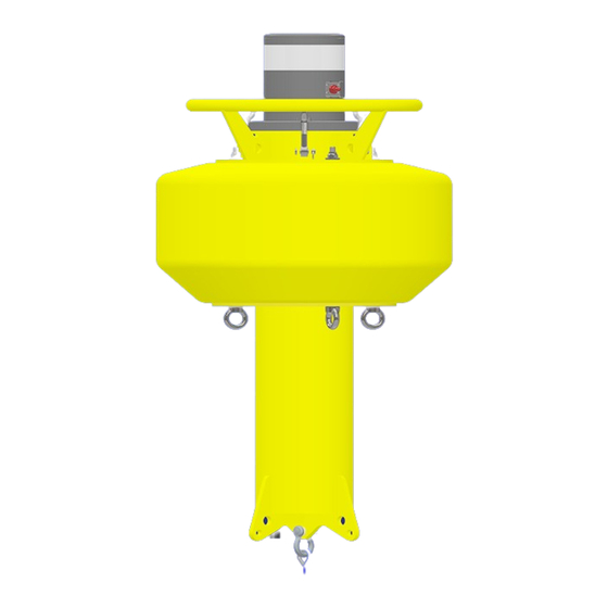
Page 4: Buoy Introduction
1. Buoy Introduction The Ocean Sonics Radio Buoy provides a way to deploy one or more synchronized icListen Smart Hydrophones and stream data remotely. The buoy is small, lightweight, and can be deployed from a small vessel by 2 people. This solution combines power, radio communication, and time synchronization with a hydrophone array. -
Page 5: Specifications
2. Buoy Mechanical Overview The Radio Buoy consists of four main components: the Buoy Body, which includes the battery pack, the TopHat which contains the electronics and connection points, the Ballast assembly, and the Radio Mast and radio. -
Page 6: Main Assemblies
Contains D-Cell batteries. Do Contains electronics. Do not in Battery Module. Do not not disassemble except lower open unless instructed. disassemble further. Ships battery plate removal. Ships Ships installed in Buoy installed in Battery Module. installed in Buoy assembly. assembly. Radio Buoy User Guide... -
Page 7: Buoy Connections
Buoy TopHat connectors A – Radio Cable Port B – Auxiliary Port for communication via laptop and test cable C – Power Enable Port D – Hydrophone cable through connector E – battery power connector Radio Buoy User Guide... -
Page 8: Replacing The Batteries
To remove old batteries, it is easiest to remove foam spacers as you progress, but make sure you place them somewhere safe (they are light and can blow away!). • When all the batteries are removed, the foam spacers may be reinstalled for safekeeping. Radio Buoy User Guide... - Page 9 When all the old batteries have been removed, insert 72 new batteries. • With the new batteries loaded, replace the lower tray and tighten the three captive screws. • You will feel tension as the battery springs are compressed. Radio Buoy User Guide...
-
Page 10: Replacing The Battery Module
When the battery module is seated, thread the two cables through the two foam inserts and plug them in. • Push the foam inserts down and install the Top-Hat. Ensure the O-ring and mating surfaces are properly cleaned and lubricated using lint-free wipes and O-ring lubricant. • The Top-Hat is a snug fit – make sure it is seated properly. • Swing the retaining bolts back into the slots and tighten until snug. Radio Buoy User Guide... -
Page 11: Assembling And Extending The Mast
The mast base can now be installed on the top hat. • Align the MCBH connector with the hole in the mast mounting plate and screw the assembly in place using the 6 M6x18 flat head Phillips screws provided. • Attach the antenna to the mast using the included bracket and hardware. Radio Buoy User Guide... - Page 12 Once the mast is at the desired height, tighten the collet by turning the upper handle clockwise. • Note that attainable mast height depends on the payload and ballast of the buoy. For shorter distance deployments, a lower mast height may be used if desired, which will reduce the ballast required. Radio Buoy User Guide...
-
Page 13: Installing The Weight Fixture
Use the two included 7/16” wrenches to tighten the fasteners. • Install the ballast weights as shown below before deployment. • Note that the PVC bushing should fit between the lowest two structural plates – the ¼-20 screws may need to be loosened before it can be inserted and retightened afterwards. Radio Buoy User Guide... - Page 14 NOTE: If no extra ballast is required, the PVC bushing must still be installed to constrain the two lower spacers. • With No added ballast, the threaded rod assembly may be omitted. BALLAST ASSEMBLY EMPTY BALLAST WITH WEIGHTS ASSEMBLY Radio Buoy User Guide...
-
Page 15: Buoy Control Gui Application Overview
7. Buoy Control GUI Application Overview The Buoy Control GUI has several basic functions to interface with the radio buoy: • Turn battery power to the hydrophone(s) on/off. • Shutdown (Reverse bias) the hydrophone(s) to power them off. • Start/Stop GPS data streaming. -
Page 16: Buoy Control Gui Getting Started
The buoy server allows GPS steaming and control of power to the hydrophones. It uses a Serial Server to distribute the GPS output over the network. It comes with a pre-configured IP address, but this may need to be changed depending on user network configurations. There are two ways to do this, through the Server web interface or with the Netburner IPSetup tool. Instructions on using both options are detailed here. Radio Buoy User Guide... -
Page 17: Server Ip Address Update Via Web Interface
Server IP Address Update via Web Interface 1. Open the Buoy Server web interface using the default IP address provided by Ocean Sonics • Username: OceanSonics • Password: OceanSonics! 2. Update the Static IP address on the Network Page if required. -
Page 18: Server Ip Address Update Using Ip Setup Tool
Server IP Address Update using IP Setup tool NetBurner provides a tool for searching the local network for any NetBurner devices and configur- ing their IP addresses. This may be found at: (https://www.netburner.com/download/ip-setup/). This is also useful if the NetBurner IP address is lost. To use the IP Setup tool, first download and install it. Searching for devices should return a result like in the below image with the currently set IP address. A new IP address may be configured by entering the desired value in the “IP” field on the left and clicking “Set”. The “Baudrate” and “Advanced” settings should not be needed. Radio Buoy User Guide... -
Page 19: Recording Gps Data On An Iclisten Hydrophone
Note: if the hydrophone shows up yellow, update IP address to work with the static IP from the Buoy Server. 4. On a web browser, go to the address bar and type /gps.html after the icListen IP. example: http://172.16.8.11/gps.html 5. Enter the IP address of the buoy server. 6. Click SET IP. 7. Click the TEST button to ensure the GPS is working. The results should be: Connecting ...Please wait, 4 NMEA strings, followed by Finish. Radio Buoy User Guide... -
Page 20: Using Buoy With Pamguard
Select Connection Type” as “Client”. The serial port number will depend on avail- ability on the host PC but will default to COM1 if it available. b. Type the buoy server IP address into the “Remote host name/port” field and use port 24. Click “Add” and then “Apply” Radio Buoy User Guide... - Page 21 5. Once the virtual COM port is set up, it should look like the image below. GPS data will be redirected to port COM1 and not be available from the Buoy Control GUI. 6. Go to Pamguard and add the NMEA Data Collection Module. Set it up so it collects real NMEA data on serial port COM1 at 9600 baud. Radio Buoy User Guide...
- Page 22 7. Add the GPS Processing Module. Under Settings -> GPS Options, set the data string to “RMC String” starting with “GN” and click OK. 8. Add the Map module. The current coordinates from the GPS will show on the bottom right corner of the map. Radio Buoy User Guide...
-
Page 23: Radio Introduction And Web Interface
11. Radio Introduction and Web Interface The Radio Buoy uses a Ubiquiti Bullet AC IP67 and 8 dB omnidirectional antenna. The Shore Side/ Access Point uses a Ubiquiti Rocket 2AC Prism with a 13 dBi omnidirectional antenna. Setup of the Access Point is straightforward, a shielded network cable should connect the radio to the PoE power supply and then the LAN port on the PoE supply should be connected to the computer or network. -
Page 24: Ubiquiti Radio Wireless Settings
The settings on the right-hand side are for the antenna and should be correctly configured on re- ceipt of the system. Ubiquiti Radio Network Settings The Network Settings can be accessed from the “Network” tab on the left of the main panel. Radio Buoy User Guide... -
Page 25: Other Information
Tools: Speed Test – Testing connection speed. Tools: Alignment – Used for verifying the alignment of the antennas. 12. Ocean Sonics Pre-Deployment Sequence For a quick setup install Ocean Sonics’ Software Programs OSL Tip: Marco, Lucy, and Buoy Control GUI on your PC prior to setting up your Ocean Sonics Buoy. - Page 26 11. Go to the Buoy Control GUI and click the “External Power Off” button. Go back to the hydrophone web interface and confirm that the battery status has changed from “Charging” or ”Not Charging” to “Discharging”. 12. Go to the spectrogram and do a tap test (tap gently on the hydrophone element with your finger and check that you see a response in the spectrograph and FFT plots). 13. Click “External Power On” if ready for deployment, or else click “Shutdown” to power down the hydrophone. 14. Disconnect the Power Enable plug unless deploying immediately. That completes the buoy functionality test. Next, the radio communication should be tested when receiving a new system or preparing for a deployment. Radio Buoy User Guide...
-
Page 27: Radio Bridge Setup And Verification
Once the radio and antenna are installed and powered on, the UISP mobile app may be used to quickly confirm the radio operation. The radio will create a management wifi network when it turns on which the app can find and connect to. The app provides a slightly limited version of the web interface for the radio setup and control. Radio Buoy User Guide... -
Page 28: Assembling Buoy For Deployment
2. Attach cables and hydrophones in configuration for deployment (see Appendix F for example). 3. Install Buoy Mast and Buoy Radio. 4. Complete the tests in the Ocean Sonics Pre-Deployment Sequence. 5. Confirm that all components are functional (Buoy Server, Radio, Hydrophone). 6. Configure Hydrophone(s) settings for deployment. (Note that the hydrophone settings may also be checked/changed once the buoy is deployed and the radio link is active). -
Page 29: Deployment
Attach test cable to the hydrophone. b. Insert the reset tool into the test cable power jack. Figure 2: Plugging power off tool into test cable. 7. Turn off the Ocean Sonics Buoy by removing the Power Enable plug. 8. Rinse the Buoy, hydrophones, and equipment with fresh water. Radio Buoy User Guide... -
Page 30: Gps Position Data Retrieval
10W should give a reasonable and slightly conservative estimate of the battery capacity usage. 18. Contact Ocean Sonics Ltd. To download Ocean Sonics Software please visit: https://sites.google.com/a/oceansonics.com/ ocean-sonics-resource-site/ Service... - Page 31 Choose Use the following IP address: i. IP address: 172.16.8.223 (Assuming the preset buoy IP address has not been changed) ii. Subnet mask: 255.255.255.0 e. Click OK 4. Go to Network Connections: Control Panel\Network and Internet\Network Connections. 5. Right Click on Wi-Fi. Radio Buoy User Guide...
- Page 32 6. Choose Properties. 7. Click on Internet Protocol Version 4 (TCP/IPv4). 8. Click on Properties. Radio Buoy User Guide...
-
Page 33: Marco Settings - Dhcp
Click Send to Device and wait for settings to be successfully sent to the unit. e. Continue this for each unit so they are all set to DHCP IP addresses. f. Units should all show up green indiscating they are ready. Radio Buoy User Guide... -
Page 34: Confirming Voltages
(pinout below). 2. Place the positive voltmeter lead (red) into pin 7 (pinout below). MCBH8F Bulkhead Connector Pinout Fully Charged Batteries should measure approximately ~ 25 V. Batteries should not be discharged past 21 V. Radio Buoy User Guide... - Page 35 22. Appendix D Sample Buoy Assembly Radio Buoy User Guide...
-
Page 36: Technical Drawing
23. Appendix E Technical Drawing Radio Buoy User Guide... - Page 37 24. Appendix F Radio settings as shipped to customer for Access Point (Rocket) and Station (Bullet). Rocket settings: Radio Buoy User Guide...
- Page 38 Bullet settings: Radio Buoy User Guide...
Need help?
Do you have a question about the Radio Buoy and is the answer not in the manual?
Questions and answers