
Related Manuals for Keystone KSTAP051PA


Summary of Contents for Keystone KSTAP051PA
- Page 1 MOBILE TYPE AIR CONDITIONER (Local Air Conditioner) Owner’s Manual IMPORTANT NOTE: Before using your air conditioner, please read North America Product this manual carefully and keep it for future reference.
-
Page 2: Table Of Contents
CONTENTS Safety Precautions Preparation before installation Before you get start product overview Installation instructions Installation overview Installation guide Operation instructions Get to know your AC Drainage guide Cleaning & maintenance Store the unit when not in use TROUBLESHOOTING... -
Page 3: Safety Precautions
Safety Precautions Must read the warning message Read Safety Precautions Before Operation and Installation To prevent death or injury to the user or other people and property damage, the following instructions must be followed. Incorrect operation due to ignoring of instructions may cause death, harm or damage. - Page 4 WARNING • Installation must be performed according • Installation must be performed according to the installation instructions. Improper to the installation instructions. Improper installation can cause water leakage, installation can cause water leakage, electrical shock, or fire. electrical shock, or fire. •...
- Page 5 CAUTION • This appliance can be used by children • Prior to cleaning or other maintenance, the aged from 8 years and above and person appliance must be disconnected from the with reduced physical, sensory or mental supply mains. capabilities or lack of experience and •...
-
Page 6: Preparation Before Installation
Before You Start Preparations before installation M a n u a l The installation must Installing your AC We recommend We’re here if you need us, be carried out in strict should take about doing this with please contact your local accordance with the 30 minutes. - Page 7 How to purchasing a mobile type air conditioner. The right air conditioner helps you cool a room e ciently. An undersized unit won't cool adequately while one that's too large will not remove enough humidity, leaving the air feeling damp. To nd the proper air conditioner, determine the square footage of the room you want to cool by multiplying the room length by its width.
- Page 8 PRODUCT INSTALLATION LOCATION Your installation location should meet the following requirements: -Make sure that you install your unit on an even surface to minimize noise and vibration. -The unit must be installed near a grounded plug, and the Collection Tray Drain (found on the back of the unit) must be accessible. -The unit should be located at least 30cm (12”) from the nearest wall to ensure proper air conditioning.
-
Page 9: Product Overview
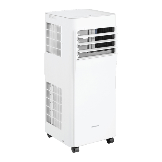
Product Overview NOTE ON ILLUSTRATIONS: All the illustrations in the manual are for explanation purpose only. Your machine may be slightly di erent. The actual shape shall prevail. The unit can be controlled by the unit control panel alone or with the remote controller. This manual does not include Remote Controller Operations, see the <<Remote Controller Instruction>>... - Page 10 Model B Control panel Remote signal receptor Handle (both sides) Air outlet louver control Air lter lever-manual adjustment upper air intake (On some models) Drain outlet Air outlet Front panel Lower air intake Bottom tray drain outlet Caster Front View Rear View Model C Control panel...
-
Page 11: Installation Overview
Installation Installation Completion Display Overview Hung Window Installation Sliding Window Installation NOTE Window Slider B Window Slider A Illustrations in this manual are for explanatory purposes. The actual shape of your indoor Extended Exhaust Hose unit may be slightly di erent. The actual Local Air Conditioner shape shall prevail. - Page 12 List of Installation Tools (not included) Saw (On some models, to shorten Screwdriver & wrench Pencil A tape measure Scissors or Knife window adaptor for narrow windows) Installation accessories NOTE Items with (*) are on some models. Slight variations in design may occur. North America Unit Adaptor (1pc) Window Slider Adaptor(1pc)
- Page 13 Other Regions Unit Adaptor (1pc) Window Slider Adaptor(1pc*) Exhaust Hose Adaptor(1pc*) Air exhaust passage(1pc*) Drain Hose (1pc) Wall Exhaust Adaptor A Security Bracket and 2 Screws (1 set*) Wall Exhaust Adaptor B (only for wall installation (with cap)(only for wall models)(1pc*) installation models)1 pc(*) Foam Seal A (Adhesive)
- Page 14 Confirm your window type (window type and opening size of di erent types) Sliding Window Installation Hung Window Installation For Optimal Performance in Operation INCORRECT CORRECT NOTE: To ensure proper function, DO NOT overextend or bend the hose. Make sure that there is no obstacle around the air outlet of the exhaust hose (in the range of 500mm) in order to the exhaust system works properly.
-
Page 15: Installation Guide
Exhaust Hose and Adaptors Installation Model A Model B Air exhaust Exhaust hose Exhaust hose passage assembly Exhaust hose Unit adaptor Window slider Unit adaptor Window slider Exhaust hose adaptor adaptor assembly Model C Model D Extended Exhaust Exhaust hose Exhaust hose hose assembly... - Page 16 Connect the Adaptor to the Unit & the Window MODEL A MODEL B Before assembly Bolt Window Sliders After assembly Bolt Window slider A Window slider B 1+2: Bolt Bolt Bolt 1+2+3: Outside Inside Bolt Bolt Bolt 1+2+3+4: Window slider A Window slider C Bolt Window slider B...
- Page 17 Foam seal A Foam seal B (Adhesive type) (Adhesive type-shorter) Hung Window Installation Foam seal A Foam seal B (Adhesive type) (Adhesive type-shorter) Sliding Window Installation Complete sealing of window Cut the adhesive foam seal A and B strips to the proper lengths, and attach them to the window sash and frame as shown.
- Page 18 Hung Window Installation Step 1: Insert the window slider assembly into the window opening. Step 2: Cut the non-adhesive foam seal C strip to match the width of the window. Insert the seal between the glass and the window frame to prevent air and insects from getting into the room. Step 3: If desired, install the security bracket with 2 screws as shown.
- Page 19 Sliding Window Installation Step 1: Insert the window slider assembly into the window opening. Step 2: Cut the non-adhesive foam seal C strip to match the height of the window. Insert the seal between the glass and the window frame to prevent air and insects from getting into the room. Step 3: If desired, install the security bracketwith 2 screws as shown.
- Page 20 Install the Exhaust Hose Assembly to the Unit Push the Exhaust hose into the airoutlet opening of the unit along the arrow direction. Hung Window Installation Sliding Window Installation Connect the Adaptor to the Unit and the Window Insert the window slider adaptor into the hole of the window slider.
-
Page 21: Operation Instructions
Get to know your AC Electronic control operating instructions 4. Display 5. Fan Function 1. POWER button Shows the set temperature while Press to control the fan speed in Power switch on/o . four steps HIGH, LOW, Cont and on Cool, or Auto mode. It shows 2. - Page 22 9. Continuous Fan function In COOL or DRY mode, press the Fan button for 3 seconds to turn on or o the continuous fan function. When the function is turned on, the Cont. fan light will illuminate, indicating the fan will run continuously. When the function is turned o , the Cont.
-
Page 23: Drainage Guide
Drainage guide Dehumidifying Mode Drainage Guide Step 1: During dehumidifying modes, remove the drain plug from the back of Remove the the unit, install the drain connector (5/8" universal female mender) with Step 2: drain plug 3/4" hose(locally purchased). For the models without drain connector, Install the just attach the drain hose to the hole. -
Page 24: Cleaning & Maintenance
Cleaning How to clean & maintenance your AC & Maintenance Air Filter & Cabinet Cleaning Clean the unit using a damp, lint-free cloth and mild detergent. Dry the unit with a dry, lint-free cloth. Maintenance Tips • Be sure to clean the air lter every 2 weeks for optimal performance. -
Page 25: Store The Unit When Not In Use
Store the Unit when not in Use Step 2 Step 3 Step 1 hours *Drain the unit‘s water collection *Please refer to the actual tray then reinstall the bottom plug, and the legend is for drain plug back in. reference only. Step6 Step4 Step 5... -
Page 26: Troubleshooting
TROUBLESHOOTING Problem Solving Common Issues The following problems are not a malfunction and in most situations will not require repairs. Problem Possible Causes Solution The Water Collection Tray is full. Turn o the unit, drain the P1 Protection Code water from the Water Collection Tray and restart the unit. Unit does not turn on when pressing In COOL mode: room... - Page 27 The design and speci cations are subject to change without prior notice for product improvement. Consult with the sales agency or manufacturer for details. Any updates to the manual will be uploaded to the service website, please check for the latest version.
Need help?
Do you have a question about the KSTAP051PA and is the answer not in the manual?
Questions and answers