Advertisement
Advertisement
Table of Contents

Subscribe to Our Youtube Channel
Related Manuals for ASA Electronics AM-30


Summary of Contents for ASA Electronics AM-30
- Page 1 Digitalized Management System for screw fastening Product Introductions AM-30 AM-45 AM-55 AM-65 AM-85 ASA ENTERPRISE CO. 2F., No.346, Sec. 6, Nanjing E. Rd., Neihu Dist., Taipei City 11470, Taiwan Tel: +886-2-27900535 Fax: +886-2-27949952 Email: asaswdvr@ms16.hinet.net Website: www.asa-tool.com...
-
Page 2: Table Of Contents
Table of Content Special Thanks to our customer ■ Thank you for choosing ASA light and powerful electric screwdriver and AM Digitalized Management System for Screw Fastening (AM controller). To ensure the tool fully utilizes its maximum performance and extend its life, please read this manual before use. -Table of Content- General Safety Warnings ..................... -
Page 3: General Safety Warnings
General Safety Warnings ■General Safety Warnings WARNING: Read all safety warnings and all instructions Failure to follow the warnings and instructions may result in electric shock, fire and/or serious injury. Save all warnings and instructions for future reference. ■Work area safety -Keep work area clean and well lit. -
Page 4: Read Before Use
Read before use Read before use ■Please read the following notices before use: ‧Set-up Notice -The AM controller should be used in dry place indoor without the presence of dust and iron grindings. -The AM controller should be positioned on a stable surface to avoid falling caused by vibration. -The AM controller should be kept away from high voltage sources and noise generating sources to avoid electromagnetic interference. -
Page 5: Declaration Of Conformity Ce/Service
Declaration of Conformity CE/Service ■Declaration of Conformity CE We (ASA Enterprise Corporation) declare under our sole responsibility that the products controller described under this manual are in conformity with the following Directives/ or standardization documents: Low Voltage Directive 2014/35/EU and EMC Directive 2014/30/EU ■Service Have your controller serviced by a qualified repair person using only identical replacement parts. -
Page 6: Product Information
-You can easily connect AM-series to your automation equipment with standard input/output signals. -Humanity operation interface where you can switch the languages between Chinese and English. Specification ■ AM Controller MODEL NO. AM-30 AM-45 AM-55 AM-65 AM-85 ITEM Counting Range of Accumulative... -
Page 7: Operation
Operation ■Parts and functions ‧Speed setting Turn the speed-setting screw through the hole on the side of the power supply with the small screw driver (standard accessory). -Turn clockwise 010 on the scale to increase the speed. -Turn counter-clockwise 100 on the scale to lower down the speed. ‧AM screwing manager-Panel keys AM Controller Return to the... - Page 8 Operation ‧Power setting and AC input socket (C13 specification) -The input voltage of AM power supply is ranged between 100-240VAC, 50/60 Hz. Please make sure you use the correct voltage to avoid any damage to the power supply. -Connect one side of the cable to the AC power socket and the other side to the electric socket (C13 specification) of the AM controller.
- Page 9 Operation ‧Indicator Light Model AM-30 AM-45 AM-55 AM-65 AM-85 Item Switch-on After switch on, flash ◎ ◎ ◎ ◎ ◎ Green light orange light three times, then turn to green light Brakes ◎ ◎ ◎ ◎ ◎ No light No DC voltage output ◎...
- Page 10 Operation ‧Output (DC) Plug -Provide power to the electric screwdriver. -Plug specification Bottom of the AM controller 5P connection 6P connection ‧OUTPUT-A: Signal output terminal (see picture 1) -A3 & A4: Switch on signal output. A3 and A4 will export no-voltage conduct signal when the electric screwdriver switched on.
- Page 11 Connect H1 to H2. You can use external controller to control (see picture 2). This connection guideline is for automation ONLY. -The connection between type AM-30 controller and the automation equipment : The JP-A can control from the external controller.
- Page 12 Operation ‧JP-B: AM Controller terminal block for external control ONLY JP-B Pin and corresponding output mode: -Under the mode WORK I/P, B5 and B6 should be conductive in order to operate. Both the AM controller and the external controller can be monitored by the operator at the same time. The signal of the sensor used in the production line can be delivered to the AM controller.
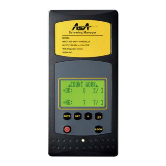
- Page 13 Operation ASA- The Operation Manual of AM Digitalized Management System for Screw Fastening Return to the operation Switch to the setting AM controller panel Selection Key page Key page Key Selection/Enter Key Screen Lock Key LCD ON/OFF Key Screen Description and function of each displayed screen Operation Guideline Screen Indication...
- Page 14 Operation [NG]:- sample fastening time, it will switch to the next screen automatically. to save and press SET to confirm and switch to screen (9) Setting the upper-limit percentage of sample fastening time. The max. 12. Set the numbers of sample on screen(9) and upper-limit percentage is 99%.
- Page 15 11. The JP terminal block for the external controller (JP-A): Please see picture 4 A5、A6: Start signal for automation ONLY. Keep pressing the lever button.(Besides AM-30) Use the external controller to control the conduction and non-conduction between the AM controller and the electric screwdriver.(AM-30 can only work on co-rotating) (see picture 1)
-
Page 16: Troubleshooting
Troubleshooting ■Troubleshooting If the screwdriver does not work properly, follow the check-list below to examine your screwdriver. If none of the following points apply to the problems you encountered, do not open the unit and contact your local sales agent immediately for further guidance. ‧The screwdriver is out of operation -Please check whether the power plug is correctly and tightly plugged into the designated power source. -
Page 17: Assembly Drawing/Parts List
Assembly Drawing... - Page 18 2 Differ from Model MODEL LABEL 1 PCS (1 SET) 2A2936 PCB SUB ASS'Y 1 SET 2A2936-MP PCB SUB ASS'Y 1 SET 2A2917-LP LED PCB SUB ASS'Y AM-30 1 PCS 6G1001 PLASTIC PLUG 1 PCS 2S2038-1 ON/OFF SWITCH 1 PCS 2G4010 AC INLET (1 SET)
- Page 19 Parts List PART NO. ITEM DESCRIPTION Q’TY AVAILABLE MODEL (1 SET) 2A2939 PCB SUB ASS'Y 1 SET 2A2939-MP PCB SUB ASS'Y 1 SET 2A2917-LP LED PCB SUB ASS'Y AM-85 1 PCS 6G1002 PLASTIC PLUG 1 PCS 2S2038-1 ON/OFF SWITCH 1 PCS 2G4010 AC INLET 1 PCS...
- Page 20 Enjoying in Technique of Assemblies Attention! The generic or unsuitable parts might seriously Retailer’s affect the power supply’s lifespan, please purchase the parts from Stamp original manufacturer to secure your rights. 2018.A.1 P#:7S1037...
Need help?
Do you have a question about the AM-30 and is the answer not in the manual?
Questions and answers