Table of Contents
Advertisement
Quick Links
Advertisement
Table of Contents

Related Manuals for ASA Electronics ChemScan mini


Summary of Contents for ASA Electronics ChemScan mini
- Page 1 ChemScan mini Mn Analyzer ® for Manganese Monitoring Installation, Operation and Maintenance Manual asaanalytics.com ASA, Inc. (Applied Spectrometry Associates) 2325 Parklawn Drive, Waukesha WI 53186 PH: 262-717-9500 FX: 262-717-9530 File: ChemScan mini Mn Analyzer O&M Manual Rev 131122W...
-
Page 2: Table Of Contents
TABLE OF CONTENTS ANALYZER DESCRIPTION Specifications / Shipping & Storage Unpacking Analyzer Inspect for Damage Contents of Installation Kit Initial Reagent Supply Yearly Maintenance Kit INSTALLATION Mounting Electrical and Output Connections Plumbing Connections Reagent Installation STARTUP Power Up Verify Sample Flow and Pump Operation Select Analysis Range Perform Initial Zero Reference Prime Injector Pump... -
Page 3: Analyzer Description
Analyzer Description The ChemScan mini Mn has been developed utilizing proven technology to provide reliable and accurate analysis of water and wastewater. The device has been designed to reduce maintenance requirements by using large ID sample tubing to minimize plugging and typically only needs quarterly reagent change out. -
Page 4: Specifications / Shipping & Storage
Isolated 4-20 mA Shipping and Storage This ChemScan mini Analyzer is shipped in a double-wall, corrugated carton suitable for protecting the analyzer from damage during normal shipping and handling. We recommend retaining this carton to provide optimum protecton for return shipping if needed. -
Page 5: Unpacking Analyzer
Unpacking Analyzer Inspect for Damage Remove the analyzer from the shipping carton. Inspect the analyzer and installation kit for damage. Report any damage to ChemScan Service. Contents of Installation Kit The installation kit provides the items necessary to install and operate the analyzer for the first year. Installation Kit Parts: ITEM PART NUMBER... -
Page 6: Installation
Installation IMPORTANT: Never mount the equipment in such a way that it is difficult to locate or operate the disconnecting device. WARNING: If this equipment is installed or used in a manner not specified in these instructions, proper operation cannot be assured, and the safety and protection provided by the equipment may be impaired. -
Page 7: Plumbing Connections
Note: A secondary 4-20 mA Auxiliary Channel (AUX) is unused. Alarm relays fused at 5 amps are provided. These are dry-contact. Usage is limited to 24 VAC. Plumbing Connections The sample line should be connected as shown in Figure 2. A pressurized side stream sample is required, with minimum sample pressure of 0.5 psi (3.4 kPa) and maximum pressures of 10 psi (68.9 kPa). - Page 8 Load, <1000 ohm Return 11x14x7" Load, <1000 ohm AUX 4-20 ChemScan mini Analyzer WEIGHT: 27 lbs (12.25 kg) DIMENSIONS: 26.0 x 9.50 x 7.0" DEEP, (66 x 24 x 18 cm) POWER: 100 - 240 VAC, 50 / 60 Hz, 1 AMP...
- Page 9 Figure 2...
- Page 10 MANGANESE CHEMISTRY ANALYZER One bottle shown, actual number may vary. Figure 3...
-
Page 11: Verify Sample Flow And Pump Operation
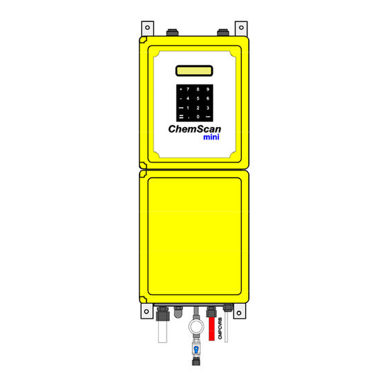
ChemScan mini Analyzer Major Components Comunications AC Power Power Supply Operator Interface Circuit Board Upper Enclosure Optics & Flow-Cell Assembly Reagent Injector Pump(s) Terminal Block Air Pump Lower Enclosure Sample Control Manifold Valve Cleaning Pump Reagent Container(s) Sample Drain Air Inlet... -
Page 12: Startup
Startup The following steps will startup the analyzer, typically in 30 – 45 minutes. • Power Up • Verify Sample Flow and Pump Operation • Select Analysis Range • Perform Initial Zero Reference • Prime Injector Pumps • Verify 4-20 mA Signals (optional) •... -
Page 13: Perform Initial Zero Reference
in the clear tubing to the flow cell. Within a minute or two the air bubbles should be replaced by cleaning solution. The analyzer cleaning pump moves approximately 60 milliliters/minute. If cleaning solution was not properly pumped, check the fittings connection on the cleaning solution tube to the instrument. -
Page 14: Prime Injector Pump
Prime Injector Pumps The reagent tubing and injector pumps need to be primed with reagents to the flow cell. Verify that the flow-cell is full of sample water. From the MAIN MENU, press “4” for Setup, then use the “+” key to display more options until 7) PRIME INJECTORS, and press the “7”... -
Page 15: Operation
Operation Menu Items The analyzer is equipped with an operator interface consisting of a display and keypad. The operational parameters can be adjusted through the operator interface. NOTE: Whenever a “+” is displayed in the lower right of the display, use the + key to display more menu choices. The keypad is used to enter numerical values and to select menu choices for the analyzer. -
Page 16: Menu Structure
MENU STRUCTURE MAIN 1) ONLINE CONTINUOUS MONITORING - Display reflects current analysis Exit ONLINE mode by pressing MAIN - Outputs are frozen at last online reading 2) SAMPLE 1) ADJUST 1) SLOPE - current slope is displayed, may be edited 2) OFFSET - current offset is displayed, may be edited 3) CALCULATE... -
Page 17: Calibration
Calibration The Analyzer has been shipped with a factory calibration. Typically this calibration is accurate enough for most applications. Lab standards can be used to verify the analyzer’s accuracy. When using a laboratory standard, allow at least 500 mL of sample to flush through the cell before the analysis. -
Page 18: Maintenance
Maintenance The analyzer has been designed to minimize the total amount of maintenance time. Typically the analyzer requires less than 2 hours of maintenance per month. Maintenance Schedule Routine maintenance of the analyzer is limited to a few periodic procedures as follows: Daily - Observe analyzer and confirm normal operation Quarterly*... -
Page 19: Maintenance Procedures
Maintenance Procedures The following pages are procedures describing the routine maintenance operations. Interrupting On-Line Operation To interrupt on-line operation the “Main Menu” key is pressed. If the security code has been set to a value other than 0, the security code must be entered. Sample Line Screens The sample line inlet is equipped with a small mesh screen to prevent the entry of large particles and debris into the system. - Page 20 Peristaltic Pump Maintenance To ensure reliable operation of this analyzer the peristaltic Air Pump requires the following maintenance procedures: 1.) The Air Pump Head Assembly requires replacement on a periodic basis – every second reagent change – typically every six months. A replacement pump head is provided in the “Startup Kit”...
-
Page 21: Peristaltic Pump - Pump Head Replacement
Peristaltic Pump – Pump Head Replacement: 1.) Place the analyzer in “Off-Line” mode by pressing the “MAIN MENU” key and close the blue handled, manual, sample valve on the strainer / inlet assembly. 2.) The “Air Pump” is located on the left side of the manifold block as shown in the photo. 3.) Sample water will drain from the upper barbed fitting when the pump tube is removed. -
Page 22: Peristaltic Pump - Full Replacement
Peristaltic Pump - Full Replacement: 1.) Place the analyzer in “Off-Line” mode by pressing the “MAIN MENU” key and close the blue-handled, manual, sample valve on the strainer / inlet assembly. 2.) The “Air Pump” is located on the left side of the manifold block as shown in the photo. The “Cleaning Pump”... -
Page 23: Flow Cell - Physical Cleaning
Flow Cell - Physical Cleaning n most applications, the acid based reagent and cleaning solution will keep the flow cell windows clean. However, in some waste-water or industrial installations or under severe operation conditions, a film may build up on the windows that the cleaning solution does not remove. (as evidenced by, for instance, less than 1 volt detector signal when doing a manual zero). -
Page 24: Retrieving Log Data From The Analyzer
Click on “Start”, “Programs”, “Accessories”, “Communication” and “HyperTerminal”. A “Connection Description” dialog box will open. Enter a file name “ChemScan mini”, where you wish, on the computer. A “ChemScan mini – HyperTerminal” communication box will open with the file name you specified. - Page 25 To observe the operational history, type GETLOG EVENTS 100 to get the last 100 events without any reading data. If you want all the data included, you can type GETLOG ALL 1000 to get all of the last 1000 log entries. To end log output, press the “Ctrl”...
-
Page 26: Analyzer Troubleshooting Guide
Analyzer Troubleshooting Guide Symptom Cause Action No Flow/ Plugged Strainer Clean or Replace Strainer Inadequate Flow Plugged Line or Valve Blow Out or Replace Plugged Items Low or No Pressure Correct to specified range Unstable Test Zero Fouled Cell Chemically Clean Cell Readings Bubbles/Air in Flow Cell Check Plumbing for Air Leaks... -
Page 27: Additional Information
Appendix A Additional Settings MAIN OUTPUTS 240V SPDT 5 AMP individually fused ALARM 1: May be set to activate when the displayed concentration is above or below the Alarm 1 setpoint. ALARM 2: May be set to activate when the displayed concentration is above or below the Alarm 2 setpoint. - Page 28 Analyzer Auxiliary I/O Terminal Block Diagram 100mA FUSE AUX OUTPUTS OUT COMMON ON-LINE BUSY READING DRAWING SAMPLE MAINTENANCE REQUIRED SPARE SPARE EXTERNAL FLOW EXTERNAL RUN/START INPUT COMMON AUX INPUTS PHONE: 262-717-9500 ASA, Inc. FAX: 262-717-9500 Applied Spectrometry Associates, Inc. DATE: 3/7/11 Analyzer Auxiliarly I/O Terminal Block FILE# AUXIO4...
-
Page 29: Analyzer Error Messages
Analyzer Error Messages: Message: [ ] [ALARM TRIPPED]: Flashing message indicating that the concentration setpoint has been reached triggering the alarm relay. [RAPID FOULING]: Analyzer successfully cleaned itself, but the flow-cell quickly refouled. To avoid depleting the cleaning solution by doing numerous, successive cleanings, further cleaning attempts are disabled. -
Page 30: Reagent Injector Pump Priming Procedure
Reagent Injector Pump Priming Procedure NOTE: Use this procedure ONLY if the injector pump does not prime using the standard Startup Procedures. When working with chemicals always follow typical lab safety procedures to protect people and equipment from chemical, electrical and other hazards. ! CAUTION: ALWAYS WEAR APPPROPRIATE EYE PROTECTION Occasionally a reagent injector pump will not prime on the initial startup of the analyzer or after extended storage. -
Page 31: Technician Level Menu
Technician Level Menu Hidden option (9) from the Main Menu screen offers the installer a series of variables. Use the + and - keys to scroll through the options. The current value is displayed, and a new value may be entered at the cursor. - Page 32 “READINGS TO AVERAGE” Specifies the number of voltage measurements from the flow cell detector to average into a “'reading”. This is a moving average, performed constantly. The normal value for this is 3. It is recommended that this value not be changed. “0) INIT LOG:: XXXX ENTER TO SEND LOG”...
-
Page 33: Maintenance Items List - Contact Information
ChemScan mini Mn Analyzer Maintenance Items List Reagent 1 (Yellow Fitting): Mn Color Reagent - ASA Part # 100219 Reagent 2 (Green Fitting): Mn Buffer Reagent - ASA Part # 100220 Cleaning Solution (Red Label) Not Provided - Available locally at retail hardware stores: The typical mixture is 1 liter of Muriatic acid (31% HCl) into 9 liters of DI water. - Page 34 Replacable Parts Display Assembly Standard- 300008 Blue- 300014 Keypad Assembly Power Supply/Circuit Breaker 300007 300003 Operator Interface Main Circuit Board Assembly 800002 300002 Optics Assembly Reagent Injector w/o Flow-Cell Tube Assembly 300004 300018 Window Plate Injector Mounting Plate 300011 440080 Flow-Cell Assembly Mini Injector Pump(s) 300020...
- Page 35 ChemScan mini Analyzer Major Components Comunications AC Power Power Supply Operator Interface Circuit Board Upper Enclosure Optics & Flow-Cell Assembly Reagent Injector Pump(s) Terminal Block Air Pump Lower Enclosure Sample Control Manifold Valve Cleaning Pump Reagent Container(s) Sample Drain Air Inlet...
Need help?
Do you have a question about the ChemScan mini and is the answer not in the manual?
Questions and answers