Advertisement
Quick Links
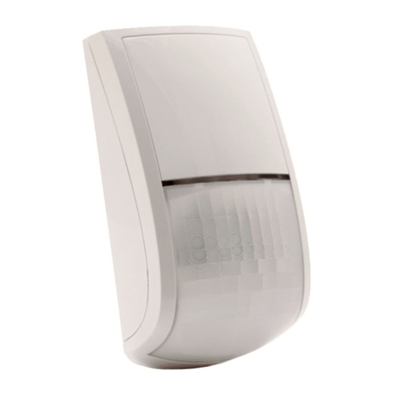
K-Band DT AM
Grade 3 Detector
Model:
RK515DTG3/RK515DTG3A
EN G LI S H
The BWare DT AM detector is the ultimate motion detector for professional
installations, incorporating both Anti-Mask and Anti-Cloak™ Technologies (ACT
™) and includes built-in end-of-line (EOL) resistors to simplify installation.
The detector employs K-Band microwave providing reduced wall penetration.
Installation / Maintenance
Mounting - The BWare DT AM can be mounted either on a flat surface or on a
wall corner (corner mounting).
1. Remove detector's front cover using a suitable tool (as described in
Figure 1).
2. Using a suitable tool, open the following knockouts on the detector's
base (see Figure 2).
Note:
If a back tamper is to be used it is mandatory to screw the tamper back
plate to the wall (or wall corner).
3. To select the correct vertical adjustment position for wide angle lens,
use the scale on the bottom right hand side of the PCB cover as follows:
Mounting height and scale position based on room size:
Mounting Height
L - LONG
S - SHORT
2.1m-2.7m (6'11"-8'10")
15m (50')
6m (20')
4. Set DIP switches and jumpers (see DIP Switch / Jumper Settings section).
Note:
Reset the detector after each change made to the settings.
5. Install the front cover back to its place (in a reverse sequence of the removal).
6. Perform a Walk test (see Walk Test section below).
Terminal Wiring (see Figure 6)
Terminal
Description
- 12 +
12VDC Input
ALARM
N.C. Relay
TAMPER
N.C. Tamper switch
FAULT/AM
Normally Closed Relay: The FAULT/AM relay opens in the following
events:
• Detector is masked (Alarm relay is also opened)
• Self test failed
• Input voltage is lower than 8VDC
LED
LED operation remote control
When an "Activation Signal"** is applied to the LED input terminal, all
LEDs will be disabled.
LEDs are enabled if nothing is connected (unless LED DIP is OFF) or
0V/12V is applied (according to the LED/SET Input Jumper position,
12V or 0V).
SET
Remote SET/UNSET control
SET: If an "Activation Signal"** is applied, anti-mask detection is disabled.
UNSET: If nothing is connected or 0V/12V is applied (according to the
LED/SET Input Jumper position, 12V or 0V) anti-mask detection is
enabled (see also "Green Line" and "Remote Self Test")
**Activation Signal-
If 12VDC is applied, and the LED/SET Input Jumper is on 12V position
(Default position)
- Or -
0V is applied and LED/SET Input Jumper is on 0V position
DIP Switch / Jumper Settings
DIP Switch
Function
SW1-1: LED
Used to determine the operation of the detector's LEDs
ON:
LEDs are enabled, allowing LED control via the LED
(Default)
input terminal
OFF:
LEDs are disabled
SW1-2: ACT
Used to determine if ACT mode is enabled or disabled
ACT Enabled
ON
Important:
Do not use ACT™ mode if you are expecting that there will
be moving objects outside the required protected area, a corridor for
example.
OFF
ACT Disabled.
(Default)
SW1-3: Green Line
The BWare DT AM includes a Green Line feature that follows environmental guidelines.
This feature disables the MW channel when the alarm system is "Unset", thus
eliminating surplus MW emission while the premises is occupied.
Green Line feature is enabled: To deactivate the MW module during
ON
"UNSET", the LEDs must also be remotely disabled by the LED terminal.
Note:
When 'Green Line' is on (Microwave off), the detector will still
activate (PIR only)
OFF
Green Line feature in disabled: MW is constantly in use.
(Default)
SW1-4: Self
Used to test detection technologies.
Test
(Local Self Test): If there is no alarm detection in the PIR
ON
channel for a period of one 1 hour, the detector will self-test. If the
local self test fails, the FAULT/AM Relay will activate.
(Remote Self Test): Remote Self Test is activated when the SET
OFF
terminal is switched from SET to UNSET mode. For remote self test
(Default)
pass, the Alarm Relay will activate for 5 seconds. If the remote self test
fails, the FAULT/AM Relay will activate.
J1 - Alarm EOL
Jumpers J1 and J2 allow the selection of Tamper and Alarm
J2 - Tamper EOL
resistance (1K, 2.2K, 4.7K, 5.6K, 6.8K) according to the control
J3 - FAULT/AM
panel (see Figure 4) Jumper J3 allows the selection of 12K for
EOL
Fault/Anti-Mask.
Follow the terminal block connection diagram in Figure 4 when
connecting the detector to a Double/Triple End Of Line
(DEOL/TEOL) Zone.
J4 - LED/SET
Used to determine the polarity of the external input.
INPUT
(Default)
See Terminal Wiring section,
See Terminal Wiring section,
LED and SET Terminals
LED and SET Terminals
Walk Test
Important:
The detector cover must be closed when applying power or
within 30 seconds after applying power, otherwise AM calibration will fail.
1. Two minutes after applying power (warm-up period), walk test the Detector over
the entire protected area to verify proper operation of the unit (see Figure 7).
2. The K-Band MW range must be adjusted using the potentiometer located on
the PCB. It is important to set the potentiometer to the lowest possible setting
that will still provide enough coverage for the inner boundary protected area
(see Figure 5).
LEDs Display
LED
State
Description
Yellow
On
PIR detection
Flashing
Trouble in PIR channel
Green
On
MW detection
Flashing
Trouble in MW channel
Blue
On
ALARM
Flashing
Anti-Masking detection
Note:
Anti Masking detection is operational in "Unset" mode
only (see Terminal Wiring section, SET terminal).
U.S. Patent Number:
This product is protected under Patent No. US 7,126,476 B2.
Other patents pending.
UKCA and CE RED Compliance Statement:
Hereby, RISCO Group declares that this equipment is in compliance with the
essential requirements of the UKCA Radio Equipment Regulations 2017 and
CE Directive 2014/53/EU.
For the UKCA and CE Declaration of Conformity please refer to our website:
www.riscogroup.com
EN 50131-1
EN 50131-2-4
Grade 3
Environmental Class II
IP30 IK04
Rapport de conformité RED
Par la présente, RISCO Group, déclare cet équipement est en conformité aux
conditions essentielles et à d'autres dispositions appropriées de la
directive 2014/53/EU.
Vous pouvez trouver la copie complète de la déclaration de conformité a la directive
2014/53/EU sur notre site web: à l'adresse suivante : www.riscogroup.com
Ce produit répond aux exigences du référentiel de certification NF324-H58 pour la
classification 3 boucliers, et de la EN 50131-2-4 et RTC 50131-2-4 Grade 3 Class II ;
PD6662:2017
Organismes de certification
AFNOR CERTIFICATION: 11 rue Francis de Pressensé 93571
LA PLAINE SAINT-DENIS Cedex, http://www.marque-nf.com
CNPP Cert. : CS22265, 27950 ST MARCEL,
http://www.cnpp.com
Certificate number: 2832000018
LEDs Display
LED
State
Description
At power-up, the LEDs will flash consecutively until the end
All LEDs Flashing
consecutively
of the warm-up period (2-3 minutes). At the end of the
warm-up period the BLUE LED will continue to flash until the
end of AM calibration.
Note:
AM and Trouble indications continue until masking is removed or trouble
is corrected.
Technical Specification
Electrical
Current consumption
16.5mA at 12VDC (typical)
39.5mA at 12VDC (max.)
Voltage requirements
9 -16VDC***
Alarm contacts
24VDC, 0.1A
Tamper contacts
24VDC, 0.1A
FAULT/AM contacts
24VDC, 0.1A
Environmental
RF immunity
According to EN50130-4
Operating temperature
-10ºC to 55ºC (14ºF to 131ºF)
Storage temperature
-20ºC to 60ºC (-4ºF to 140ºF)
MW operating frequency
24Ghz
Power Output
20dBm Max.
Current consumption
16.5mA
Optical
Filtering
White Light Protection
Physical
Size
127.6 x 64.2 x 46.6 mm (5 x 2.5 x 1.84 in.)
Weight
120 gr. (4.2 oz.)
*** Power to be supplied by 5A max. power source using safety approved
wires, with a min Gauge of 20AWG.
U.S.A Tel: +1-631-719-4400 support-usa@riscogroup.com
UK Tel: 44-(0)-161-655-5500 support-uk@riscogroup.com
ITALIANO
Il rivelatore BWare DT AM è un rivelatore di movimento che integra le tecnologie
più avanzate per le installazioni professionali. Questo rivelatore include sia la
tecnologia Anti-Mask che quella Anti-Cloak™ (ACT™) ed ha le resistenze di fine
linea integrate nel circuito per semplificarne al massino l'installazione.
Il rivelatore BWare DT AM utilizza la microonda in banda K la quale consente
una penetrazione ridotta attraverso i muri.
Installazione / Manutenzione
Installazione - Il rivelatore BWare DT AM può essere installato sia su di una
superficie piana che ad angolo.
1. Rimuovere il coperchio del rivelatore utilizzando un attrezzo appropriato
(come descritto nella Figura 1).
2. Utilizzando uno strumento appropriato aprire i fori a sfondare, di seguito elencati,
della base del contenitore come illustrato in Figura 2.
Nota:
Se deve essere utilizzato il tamper antirimozione è obbligatorio avvitare al
muro (o angolarmente al muro) la linguetta del tamper antirimozione.
3. Per selezionare la posizione corretta della scheda elettronica con la lente
grandangolo montata, usare i riferimenti ( LONG / SHORT) situati nella parte
inferiore destra della scheda elettronica seguendo le indicazioni della tabella di
seguito illustrata:
Altezza di installazione e regolazione scheda elettronica in funzione
dell'areadi copertura:
Altezza di installazione
L - LONG
S - SHORT
2.1m-2.7m
15m
4. Predisporre i ponticelli e i microinterruttori (Vedere la sezione relativa).
Nota:
Ad ogni modifica delle predisposizioni/regolazioni, effettuare sempre un
reset del rivelatore rimuovendo e applicando tensione.
5. Rimontare il coperchio frontale e stringere la vite di blocco coperchio.
6. Effettuare una prova di copertura (Sezione Prova di movimento vedere in basso).
Cablaggio Morsettiera (vedere Figura 6)
Morsetto
Descrizione
- 12 +
Ingresso di alimentazione 12V
ALARM
Relé N.C.
TAMPER
Interruttore N.C.
FAULT/AM
Relé N.C.: Il relé FAULT/AM si attiva per gli eventi seguenti:
Il rivelatore è mascherato (anche il relé di allarme viene attivato)
L'auto-test del sensore è fallito
L'ingresso di alimentazione è minore di 8V
LED
Controllo remoto dei LED e funzione GREEN LINE (con
microinterruttore SW1-3 in posizione ON)
Quando viene applicato un "Segnale di Attivazione"** al morsetto LED,
tutti i LED vengono disabilitati e, se il microinterruttore GREEN LINE è in
ON, la sezione microonda viene disabilitata.
Nota:
affinché la microonda venga disabilitata non ci deve essere alcun
comando sul morsetto SET.
I LED sono abilitati se al morsetto LED non è collegato niente (a meno che
il ponticello LED sia estratto).
or MW
SET
Controllo remoto dello stato impianto
Stato Inserito: Quando viene applicato un "Segnale di Attivazione"** a
questo morsetto, il circuito di Anti-Mask viene disabilitato
Stato Disinserito: Se all'ingresso non viene collegato niente il circuito
Anti-Mask è abilitato (vedere anche la tabella di predisposizione ponticelli
e microinterruttori riferita alla funzione "Green Line" e "Auto-test
Sensore".
**Per Segnale di attivazione si intende quanto segue-
- Viene applicata una tensione 12 Vcc e il ponticello LED/SET Input è nella
posizione 12V (posizione di default)
.
- Viene applicato un riferimento di alimentazione 0V e il ponticello LED/SET Input
è nella posizione 0V
Predisposizione microinterruttori e ponticelli
Microint./Pontic.
Funzione
SW1-1: LED
Usato per abilitare o disabilitare il funzionamento dei LED.
ON
I LED sono abilitati ed è possibile anche controllarli via comando
(Default)
remoto tramite l'ingresso LED.
OFF
I LED sono disabilitati. Non è possibile alcun controllo remoto.
SW1-2: ACT
Usato per abilitare o disabilitare la funzione ACT
ON
ACT abilitato
OFF
ACT disabilitato.
(Default)
SW1-3: Green Line
BWare DT AM include la funzione Green Line che evita emissioni radio superflue
nell'ambiente. Questa funzione disabilita il canale a microonda (MW) quando il sistema
di sicurezza è disinserito.
La funzione Green Line è abilitata: Per disabilitare la sezione
microonda (MW) a sistema DISINSERITO va applicato un comando
di attivazione al morsetto LED (0V o 12V in funzione della polarità
ON
configurata tramite il ponticello LED/SET INPUT). Anche i LED
verranno in questo caso disabilitati. La sezione microonda viene
disabilitata in questo modo solo se al morsetto SET non viene
applicata alcuna tensione.
Nota:
Quando la funzione Green Line è attiva (Microonda spenta), il
rivelatore si attiva usando la sola sezione ad infrarossi (PIR).
OFF
La funzione Green Line è disabilitata. La sezione a microonda (MW) è
(Default)
sempre accesa.
Standard Limited Product Warranty ("Limited Warranty")
RISCO Ltd. ("RISCO") guarantee RISCO's hardware products ("Products") to be free from defects in materials and workmanship when used and stored under normal
conditions and in accordance with the instructions for use supplied by RISCO, for a period of (i) 24 months from the date of delivery of the Product
(the "Warranty Period"). This Limited Warranty covers the Product only within the country where the Product was originally purchased and only covers Products
purchased as new.
Contact with customers only. This Limited Warranty is solely for the benefit of customers who purchased the Products directly from RISCO or from an authorized
distributor of RISCO. RISCO does not warrant the Product to consumers and nothing in this Warranty obligates RISCO to accept Product returns directly from end users
who purchased the Products for their own use from RISCO's customer or from any installer of RISCO, or otherwise provide warranty or other services to any such
end user directly. RISCO's authorized distributor or installer shall handle all interactions with its end users in connection with this Limited Warranty. RISCO's authorized
distributor or installer shall make no warranties, representations, guarantees or statements to its end users or other third parties that suggest that RISCO has any
warranty or service obligation to, or any contractual privy with, any recipient of a Product.
Remedies. In the event that a material defect in a Product is discovered and reported to RISCO during the Warranty Period, RISCO shall accept return of the defective
Product in accordance with the below RMA procedure and, at its option, either (i) repair or have repaired the defective Product, or (ii) provide a replacement product to
the customer.
Return Material Authorization. In the event that you need to return your Product for repair or replacement, RISCO will provide you with a Return Merchandise
Authorization Number (RMA#) as well as return instructions. Do not return your Product without prior approval from RISCO. Any Product returned without a valid,
unique RMA# will be refused and returned to the sender at the sender's expense. The returned Product must be accompanied with a detailed description of the defect
discovered ("Defect Description") and must otherwise follow RISCO's then-current RMA procedure published in RISCO's website at www.riscogroup.com in connection
with any such return. If RISCO determines in its reasonable discretion that any Product returned by customer conforms to the applicable warranty
("Non-Defective Product"), RISCO will notify the customer of such determination and will return the applicable Product to customer at customer's expense. In addition,
RISCO may propose and assess customer a charge for testing and examination of Non-Defective Product.
Entire Liability. The repair or replacement of Products in accordance with this Limited Warranty shall be RISCO's entire liability and customer's sole and exclusive
remedy in case a material defect in a Product is discovered and reported as required herein. RISCO's obligation and this Limited Warranty are contingent upon the
full payment by customer for such Product and upon a proven weekly testing and examination of the Product functionality.
Limitations. This Limited Warranty is the only warranty made by RISCO with respect to the Products. The warranty is not transferable to any third party. To the
maximum extent permitted by applicable law, this Limited Warranty shall not apply and will be void if: (i) the conditions set forth above are not met (including, but not
limited to, full payment by customer for the Product and a proven weekly testing and examination of the Product functionality); (ii) if the Products or any part or
component thereof: (a) have been subjected to improper operation or installation; (b) have been subject to neglect, abuse, willful damage, abnormal working conditions,
failure to follow RISCO's instructions (whether oral or in writing); (c) have been misused, altered, modified or repaired without RISCO's written approval or combined with,
or installed on products, or equipment of the customer or of any third party; (d) have been damaged by any factor beyond RISCO's reasonable control such as, but not
limited to, power failure, electric power surges, or unsuitable third party components and the interaction of software therewith or (e) any failure or delay in the
performance of the Product attributable to any means of communication provided by any third party service provider, including, but not limited to, GSM interruptions,
lack of or internet outage and/or telephony failure. BATTERIES ARE EXPLICITLY EXCLUDED FROM THE WARRANTY AND RISCO SHALL NOT BE HELD
RESPONSIBLE OR LIABLE IN RELATION THERETO, AND THE ONLY WARRANTY APPLICABLE THERETO, IF ANY, IS THE BATTERY MANUFACTURER'S
WARRANTY. RISCO does not install or integrate the Product in the end user's security system and is therefore not responsible for and cannot guarantee the
performance of the end user's security system which uses the Product or which the Product is a component of.
This Limited Warranty applies only to Products manufactured by or for RISCO. Further, this Limited Warranty does not apply to any software (including operating system)
added to or provided with the Products or any third-party software, even if packaged or sold with the RISCO Product. Manufacturers, suppliers, or third parties other than
RISCO may provide their own warranties, but RISCO, to the extent permitted by law and except as otherwise specifically set forth herein, provides its Products "AS IS".
Software and applications distributed or made available by RISCO in conjunction with the Product (with or without the RISCO brand), including, but not limited to system
software, as well as P2P services or any other service made available by RISCO in relation to the Product, are not covered under this Limited Warranty. Refer to the
Terms of Service at: www.riscocloud.com/warranty for details of your rights and obligations with respect to the use of such applications,
software or any service. RISCO does not represent that the Product may not be compromised or circumvented; that the Product will prevent any personal injury or
property loss by burglary, robbery, fire or otherwise, or that the Product will in all cases provide adequate warning or protection. A properly installed and maintained alarm
may only reduce the risk of a burglary, robbery or fire without warning, but it is not insurance or a guarantee that such will not occur or will not cause or lead to personal
injury or property loss. CONSEQUENTLY, RISCO SHALL HAVE NO LIABILITY FOR ANY PERSONAL INJURY, PROPERTY DAMAGE OR OTHER LOSS BASED ON
ANY CLAIM AT ALL INCLUDING A CLAIM THAT THE PRODUCT FAILED TO GIVE WARNING.
EXCEPT FOR THE WARRANTIES SET FORTH HEREIN, RISCO AND ITS LICENSORS HEREBY DISCLAIM ALL EXPRESS, IMPLIED OR STATUTORY,
REPRESENTATIONS, WARRANTIES, GUARANTEES, AND CONDITIONS WITH REGARD TO THE PRODUCTS, INCLUDING BUT NOT LIMITED TO ANY
REPRESENTATIONS, WARRANTIES, GUARANTEES, AND CONDITIONS OF MERCHANTABILITY, FITNESS FOR A PARTICULAR PURPOSE, TITLE AND
WARRANTIES AGAINST HIDDEN OR LATENT DEFECTS, TO THE EXTENT PERMITTED BY LAW. WITHOUT LIMITING THE GENERALITY OF THE FOREGOING,
RISCO AND ITS LICENSORS DO NOT REPRESENT OR WARRANT THAT: (I) THE OPERATION OR USE OF THE PRODUCT WILL BE TIMELY, SECURE,
UNINTERRUPTED OR ERROR-FREE; (ii) THAT ANY FILES, CONTENT OR INFORMATION OF ANY KIND THAT MAY BE ACCESSED THROUGH THE PRODUCT
SHALL REMAIN SECURED OR NON DAMAGED. CUSTOMER ACKNOWLEDGES THAT NEITHER RISCO NOR ITS LICENSORS CONTROL THE TRANSFER OF
DATA OVER COMMUNICATIONS FACILITIES, INCLUDING THE INTERNET, GSM OR OTHER MEANS OF COMMUNICATIONS AND THAT RISCO'S PRODUCTS,
MAY BE SUBJECT TO LIMITATIONS, DELAYS, AND OTHER PROBLEMS INHERENT IN THE USE OF SUCH MEANS OF COMMUNICATIONS. RISCO IS NOT
RESPONSIBLE FOR ANY DELAYS, DELIVERY FAILURES, OR OTHER DAMAGE RESULTING FROM SUCH PROBLEMS. RISCO WARRANTS THAT ITS
PRODUCTS DO NOT, TO THE BEST OF ITS KNOWLEDGE, INFRINGE UPON ANY PATENT, COPYRIGHT, TRADEMARK, TRADE SECRET OR OTHER
INTELLECTUAL PROPERTY RIGHT IN ANY EVENT RISCO SHALL NOT BE LIABLE FOR ANY AMOUNTS REPRESENTING LOST REVENUES OR PROFITS,
PUNITIVE DAMAGES, OR FOR ANY OTHER INDIRECT, SPECIAL, INCIDENTAL, OR CONSEQUENTIAL DAMAGES, EVEN IF THEY WERE FORESEEABLE OR
RISCO HAS BEEN INFORMED OF THEIR POTENTIAL.
POTENTIAL.
© RISCO Group 04/2024 5IN3032 D
Predisposizione microinterruttori e ponticelli
Microint./Pontic.
SW1-4: Self
Usato per testare le tecnologie di rilevazione.
Test
(Auto-test locale): Se non viene rilevata alcuna attivazione del canale
ON
PIR o MW per 1 ora, il rivelatore eseguirà un auto-test. Se il test fallisce,
l'uscita a relè FAULT/AM verrà attivata.
(Auto-test remoto): L'Auto-test remoto si attiva quando il morsetto
SET viene portato dalla condizione di Impianto INSERITO (Comando
di attivazione applicato) alla condizione di impianto DISINSERITO
OFF
(nessuna tensione applicata). A conferma che l'auto-test remoto è
(Default)
stato superato l'uscita a relé di allarme si attiverà per 5 secondi.
Se il test remoto fallisce, l'uscita a relè FAULT/AM verrà attivata.
I ponticelli J1 e J2 permettono la selezione dei valori resistivi da
J1 - Alarm EOL
assegnare ai circuiti di Tamper e di Allarme (1K, 2.2K, 4.7K, 5.6K,
J2 - Tamper EOL
6.8K) in funzione della centrale d'allarme utilizzata (vedere la
J3 - FAULT/AM EOL
Figura 4 in basso). Il ponticello J3 inoltre, permette la selezione
Ponticelli Per
di una resistenza di 12K per supervisionare il circuito
resistenze EOL
Anomalia/Anti-Mask.
Seguire lo schema di collegamento dei morsetti illustrato in
Figura 4 quando si vuole collegare il sensore ad una centrale
d'allarme usando il doppio o il triplo bilanciamento resistivo
(DEOL/TEOL).
J4- LED/SET
Usato per impostare la polarità dei comandi di attivazione per
INPUT
gli ingressi LED e SET.
(Default)
Posizionato sul lato 12V richiede come
comando di attivazione una tensione
positiva. Fare riferimento alla sezione
relativa il Cablaggio Morsettiera,
morsetti LED e SET.
Prova di movimento (Walk Test)
Importante:
Dopo aver alimentato il rivelatore, chiudere il coperchio entro 30
secondi per poter effettuare correttamente la fase di calibrazione del circuito di
antimascheramento (AM).
1. Due o tre minuti dopo aver alimentato il rivelatore (inizializzazione) effettuare
la prova di copertura dell'area da proteggere verificando la risposta del rivelatore
tramite l'accensione dei LED (vedere Figura 7).
2. La portata della microonda va regolata tramite l'apposito potenziometro situato
sulla scheda elettronica. Regolare il potenziometro della microonda al minimo
possibile riferito all'area da proteggere (vedere Figura 5).
LED Stato Descrizione
LED
Stato
Giallo
Illuminato
Lampeggiante
Verde
Illuminato
Lampeggiante
Blu
Illuminato
Lampeggiante
6m
Tutti i LED Lampeggianti
consecutivamente
Nota:
L'indicazione di Mascheramento e/o Anomalia persiste fino a quando la
causa non viene rimossa.
Specifiche Tecniche
Elettriche
Assorbimento di corrente
Alimentazione richiesta
Contatti di allarme
Contatti Tamper
Contatti FAULT/AM
Ambientali
Immunità RF
Temp. funzionamento
Temp. stoccaggio
Frequenza di funzionamento
MW
Potenza trasmessa
Assorbim. di Corrente
Ottica
Filtro
Fisiche
Dimensioni
Peso
ITALY Tel: +39-02-66590054
FRANÇAIS
Le détecteur BWare DT AM est le dernier détecteur de mouvements pour les
installations professionnelles, et intègre les technologies Anti-Masque et
Anti-Camouflage (ACT™), ainsi que des résistances de fin de ligne (EOL)
pour simplifier l'installation. Le détecteur utilise un module Hyper Fréquence
en bande K, qui permet une réduction de la pénétration à travers les murs.
De plus, le détecteur est immunisé aux champs magnétiques, et ne sera pas
perturbé à l'approche d'un aimant.
Installation
Montage - l'BWare DT AM peut être installé soit sur une surface plane soit en
coin (gauche ou droit).
1. Retirer le détecteur de couvercle frontal a l'aide d'un outil adequat (décrit
son la Figure 1).
2. A l'aide d'un outil adequat, ouvrez les pastilles pré-percées correspon
dantes sur la báse du d tecteur (cf.Figure 2).
En cas d'utilisation d'une autoprotection arrière, il est impératif de
Remarque:
fixer la plaque de cette dernière en la vissant au mur (ou à l'angle du mur).
3. Pour définir le bon réglage vertical, positionnez l'appareil en LENTILLE
GRAND ANGLE.
Servez-vous de l'échelle figurant sur le côté inférieur droit de la carte PCB
de couvercle (cf. Figure 7) comme suit :
Hauteur de montage et position selon la taille de la pièce :
Hauteur de montage
2.1m-2.7m (6'11"-8'10")
4. Réglez les cavaliers (cf. § Commutateur DIP et cavaliers Réglages).
Remarque:
Il est conseillé de réinitialiser le détecteur après chaque
modification apportée au réglage.
5. Replacez le couvercle frontal (en inversant pour cela l'ordre des étapes de
la procédure de retrait).
6. Exécutez un test de passage (cf. §Test de passage ci-dessous).
Câblage des Terminaux (cf. Figure 6)
Terminal
Description
- 12 +
Entrée 12VCC
ALARM
Relais N.F., 24VCC, 0,1A
TAMPER
Relais N.F., 24VCC, 0,1A
Câblage des Terminaux (cf. Figure 5)
Funzione
Terminal
FAULT / AM
LED
SET
**Signal d'Activation-
Si une tension de 12VCC est appliquée et que le Cavalier d'entrée LED/SET
est en position 12V (Défaut de position)
Si la Terre (GND) est reliée, le Cavalier d'entrée LED/SET est en position 0V.
Commutateur DIP et cavaliers Réglages
DIP/Cavalier
SW1-1: LED
Posizionato su 0V richiede come
comando di attivazione un riferimento
Marche (ON)
negativo di alimentazione 0V. Fare
(Défaut)
riferimento alla sezione relativa il
Cablaggio Morsettiera, morsetti LED
Arrêt (OFF)
e SET.
SW1-2: ACT
Marche (ON)
Arrêt (OFF)
(Défaut)
SW1-3: Green Line
Le BWare DT AM intègre la fonction Green Line, qui suit les recommandations
environnementales. Cette fonction désactive le canal hyper fréquence quand le
système d'alarme est désarmé, pour éliminer le surplus d'émissions HF quand les
locaux sont occupés.
Descrizione
Marche (ON)
Rilevazione del canale PIR
Anomalia del canale PIR
Rilevazione del canale MW
Arrêt (OFF)
Anomalia del canale MW
(Défaut)
ALLARME
SW1-4:
Rilevazione circuito Anti-Mask
Test
automatique
Nota:
La rilevazione del canale Anti-Mask può essere
attiva solo ad impianto "Disinserito" (Consultare la
sezione del Cablaggio morsettiera, morsetto SET).
Marche (ON)
All'alimentazione tutti i LED lampeggiano in sequenza
fino alla fine del periodo di inizializzazione (2-3 minuti).
Alla fine del periodo di inizializzazione il LED BLU
Arrêt (OFF)
continuerà a lampeggiare fino alla fine della fase di
(Défaut)
inizializzazione del canale Anti-Mask.
J1 - Alarm EOL
J2 - Tamper EOL
J3 - FAULT / AM EOL
Cavaliers TEOL
16.5mA a 12V- (Nominale)
39.5mA a 12V- (Massimo)
da 9V- a 16V-
J4 - Entrée
24V- 0.1A
LED/SET
24V- 0.1A
24V- 0.1A
Conforme alle norme EN50130-4
da -10ºC a 55ºC
da -20ºC a 60ºC
24Ghz
Cf. § Câblage des Terminaux, bornes de
connexion LED et SET (Mise en service).
20 dBm Max.
16.5mA
Test de passage
Important :
Protezione contro le luci bianche
les 2 minutes pour que la période d'initialisation AM (Anti-Masque) démarre.
1. Deux minutes après avoir réalisé la mise sous tension (séquence
127.6 mm x 64.2 mm x 46.6 mm
d'échauffement), effectuez un test de passage pour vérifier l'efficacité du
détecteur sur la totalité de la zone à protéger.
120 gr.
2. Assurez-vous d'avoir bien réinstallé le couvercle frontal avant de mettre le
support-it@riscogroup.com
détecteur sous tension (cf. Figure 7).
3. Le potentiomètre situé sur la carte PCB permet de régler la portée de détection
hyperfréquence. Il est important de régler le potentiomètre sur le niveau le plus
bas possible qui fournira cependant une couverture suffisante sur la totalité de
la zone à protéger (cf. Figure 5).
Affichage LED
LED
Jaune
Verte
Bleu
Toutes
diodes LED
Remarque:
cause du masquage ou réparation de la panne.
L - LONG
C - COURT (SHORT)
Spécifications techniques
15m (50')
6m (20')
Electriques
Consommation électrique
Tension requise
Contacts d'alarme
Temps minimal de changement d'état:
Contacts d'autoprotection
Contacts FAULT/AM
Rétsistance de la boucle de Détection: Etat ouvert: plus que 10 8
Description
Sortie normalement fermée : La sortie FAULT/AM s'ouvre dans les
cas suivants :
• Détection ou neutralisation d'un masquage,
• Echec du test automatique,
• Tension d'entrée inférieure à 8VCC.
Contrôle à distance des indicateurs LED
Lorsqu'un "Signal d'Activation"** est appliqué à l'entrée LED du bloc
des terminaux ou bornes de connexion, les indicateurs LED se
désactivent (cf. aussi l'entrée Test automatique dans le tableau
consacré au Commutateur DIP et cavaliers Réglages).
Les voyants LED sont activés si rien n'est relié (sauf si le cavalier
LED est éteint (OFF).
Contrôle à distance de la mise en Service (SET) / mise en
Inactivité du système (UNSET).
SET (mise en service): Si un "Signal d'Activation"** est appliqué, la
détection de masquage est désactivé (en configuration de catégorie 2).
UNSET (mise en inactivité) : Si aucune connexion n'est appliquée
ou que la Terre (GND/12V) est reliée (selon la position du Cavalier
d'entrée LED/SET, à 12V ou 0V), la détection de masquage est
activée (cf. également les entrées "Green Line" et "Test automatique
à distance" dans le tableau consacré au Réglage des cavaliers).
-Ou-
Fonction
Définit le fonctionnement des indicateurs LED du détecteur.
L'activation des indicateurs LED dépend du paramétrage du contrôle à
distance de leur fonctionnement (cf. § Câblage des Terminaux, borne
de connexion LED).
Les indicateurs LED sont désactivés.
Définit si le mode ACT est activé ou non
ACT activé.
Important !
N'utilisez pas le mode ACT™ dans une zone en dehors de
laquelle le passage d'objets en mouvement vous paraît logique et
attendu, un couloir par exemple.
ACT désactivé.
La fonction Green Line est activée : Pour désactiver le module HF
pendant le désarmement, les LEDs doivent aussi être désactivées par
le terminal de connexion LED.
Note :
Quand le Green Line est activé (HF désactivé), le détecteur
sera toujours actif (IRP seul).
Green Line désactivé (OFF): le canal HF est constamment activé.
Permet de tester la capacité de détection des canaux IRP et HF.
(Test automatique local): si aucune détection n'est décelée sur le canal
IRP ou HF pendant une période d'une heure, le détecteur exécute un
test automatique. En cas d'échec du test automatique local, le relais
FAULT/AM.
(Test automatique à distance): le test automatique à distance s'active
lorsque le terminal de réglage (SET) passe du mode de mise en service
(SET) à celui d'inactivité du système (UNSET).
Si le test automatique à distance réussit, le relais d'alarme s'active
pendant 5 secondes. Si le test automatique à distance échoue, le relais
FAULT/AM.
Les cavaliers J1, J2 et J3 permettent de sélectionner les
résistances EOL (fin de ligne) d'Autoprotection, Alarme et
FAULT/AM (1K, 2,2K, 4,7K, 5,6K, 6,8K et 12K) en fonction de la
centrale (cf. Figure 4 ci-dessous).
Suivez les indications du diagramme de connexion du bloc des
terminaux de la Figure 4 pour relier le détecteur à une zone EOL
Double/Triple (DEOL/TEOL).
Détermine la polarité de l'entrée externe.
(Défaut)
Cf. § Câblage des Terminaux, bornes de
connexion LED et SET (Mise en service).
Après la mise sous tension du détecteur, fermer le couvercle dans
Position
Signification
Allumée (ON) Détection IRP
Clignotante
Panne de canal IRP
Allumée (ON)
Détection HF (hyperfréquence)
Clignotante
Panne de canal HF
Allumée (ON)
Indique une ALARME
Clignotante
Anti-masque
Remarque:
La détection Anti-masque est opérationnelle
en mode "UNSET" (Inactivité du système) seulement
(cf. § Câblage des Terminaux, terminal de mise en
service (SET).
Clignotante
Lors de la mise sous tension, les diodes LED clignotent de
manière ininterrompue, l'une après l'autre, jusqu'à la fin de
l'une après
la séquence d'échauffement (2 à 3 minutes). A la fin de ce
l'autre
laps de temps, le voyant LED BLEU continue à clignoter
jusqu'à la fin du lancement de l'AM (pour mettre un terme
au clignotement, fermez le couvercle).
Les indications AM et Panne persistent jusqu'à élimination de la
16.5 mA à 12VCC (en utilisation typique)
39.5 mA à 12VCC (max. avec tous les voyants
LED allumés)
9 -16VCC
24VCC, 0,1A
2.2 seconds
24VCC, 0,1A
24VCC, 0,1A
Etat fermé: moins que 8 ohm
Advertisement

Subscribe to Our Youtube Channel
Related Manuals for Risco BWare RK515DTG3A


Summary of Contents for Risco BWare RK515DTG3A
- Page 1 à d’autres dispositions appropriées de la or installed on products, or equipment of the customer or of any third party; (d) have been damaged by any factor beyond RISCO’s reasonable control such as, but not directive 2014/53/EU.
- Page 2 Desarmado (UNSET): Si no hay nada conectado o se aplican 0V/12V Nota: Todos os detectores da RISCO Group que possuem o sistema de 5 seconden actief zijn. Indien de zelf-test op afstand faalt zal de (según la posición del Puente LED/SET Input, 12V ó 0V) se hablita el anti-máscara através de Infravermelho Ativo, possuem uma proteção contra luz...
Need help?
Do you have a question about the BWare RK515DTG3A and is the answer not in the manual?
Questions and answers