Table of Contents
Advertisement
Available languages
Available languages
Quick Links
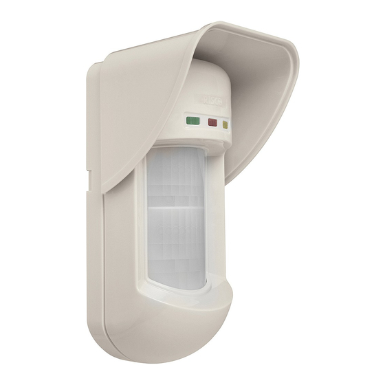
Dual Technology Outdoor Detector
Rivelatore da Esterno a Doppia Tecnologia
Detector de Exterior de Doble Tecnología
Détecteur extérieur à double technologie
Detector Externo de Dupla Tecnologia
Dual Technology-Buitendetector
WatchOUT 315DT
Installation Instructions - Relay & BUS Modes
Istruzioni per l'installazione in modalità Relé e BUS
Instrucciones de Instalación - Modos Relé y BUS
Guide d'installation - Modes Relais et BUS
Instruções de Instalação - Modos Relé & BUS
Relais- & BUS-modusinstallatie-instructies
EN
IT
ES
FR
PR
NL
Advertisement
Chapters
Table of Contents

Related Manuals for Risco WatchOUT eXtreme RK315DT0000C


Summary of Contents for Risco WatchOUT eXtreme RK315DT0000C
- Page 1 Dual Technology Outdoor Detector Rivelatore da Esterno a Doppia Tecnologia Detector de Exterior de Doble Tecnología Détecteur extérieur à double technologie Detector Externo de Dupla Tecnologia Dual Technology-Buitendetector WatchOUT 315DT Installation Instructions - Relay & BUS Modes Istruzioni per l’installazione in modalità Relé e BUS Instrucciones de Instalación - Modos Relé...
- Page 2 WatchOUT 315DT Installation Manual...
-
Page 3: Table Of Contents
Table of Contents Relay Mode Installation ......................4 Introduction ..........................4 Mounting ............................ 4 Mounting Considerations ......................4 Wall Mount Installation......................5 Flat Mounting: ......................... 5 45° angle Mounting (Left side mounting) ................5 Changing Back Tamper position .................... 6 Terminal Wiring .......................... -
Page 4: Relay Mode Installation
The detector can operate as a regular relay detector connected to any control panel, or as a BUS accessory when connected to RISCO Group's ProSYS control panel via the RS485 BUS, thus having unique remote control and diagnostic capabilities. -
Page 5: Wall Mount Installation
Wall Mount Installation Figure 1 Figure 2 Note: The installation knockouts numbering are marked on the back plate. 1. Open WatchOUT front cover (unlock C1, Figure 1). 2. Release internal base (unlock I1, Figure 2). 3. Select mounting installation as follows: Flat Mounting: Open knockouts on external base (Figure 3). -
Page 6: Changing Back Tamper Position
Figure 5 Changing Back Tamper position Left Side The back tamper is by default secured on the right Tamper side of the internal base (rear view). If you wish to move it to the left side (rear view), do the following Right Side (Figure 5): Tamper... -
Page 7: Dip Switch Settings
DIP Switch Settings DIP 4: Anti masking Sensitivity On: High Off: Low Factory Defaults DIP 5: Detector's optics On: Barrier / Long range Off: Wide angle DIP 6: Red LED /3 LED DIP 1: LEDs operation On: Red LED only On: LEDs Enabled Off: 3 LEDs Off: LEDs Disabled... -
Page 8: Relay Mode / Bus Mode Jumper
Relay Mode / BUS Mode Jumper Relay BUS Mode Mode J-BUS jumper (located on the PCB between the red and green LEDs) is used to define the detector’s mode of operation as follows: Standard Swivel Installation The Outdoor detector packaging contains a standard swivel for flexible installation. Please follow the instructions below for mounting the detector with the Standard Swivel: 1. - Page 9 Secure CSMA to the wall through points (M1, M4). Insert external cables and tamper wires from the conduit through the swivel wires passage of the swivel (Figure 6, Detail A). Secure swivel to the wall through holes S1, S3, S6 and S8. Note: The Tamper spring S5 (Figure 7) should make contact with the wall through the tamper spring holes M2 or M3 on the CSMA.
-
Page 10: Replacing A Lens
Note: The screw has to pass through External Base and locked to the swivel. Figure 8 Replacing Lenses 1. Unlock the six screws that hold the lens holding sleeve from the back of the front cover. 2. To release the protective sleeve, gently push the lens from the external side of the front cover. 3. -
Page 11: Lenses Types
Lens Types Wide angle lens (RL300) / Wide angle lens (RL300): Low installation - Pet lens (RL300F) : Side View Top view Feet Typical Installation Height: 2.2m (7'2") Meters 14 15 Feet Low installation - Pet lens (RL300F) : Side view 90°... -
Page 12: Technical Specification
Technical Specification Electrical Current consumption 30mA at 12 VDC (Stand by) 42mA at 12 VDC (MAX with LED ON) Voltage requirements 9 -16 VDC Alarm contacts 24 VDC, 0.1A AM contacts 24 VDC, 0.1A Dust output Open collector 70mA max Power Output 10.587GHZ: 10dbm Typ. -
Page 13: Ul Compliance Section
UL Compliance Section To comply with UL, note the following: The unit is intended for outdoor installation where unwanted alarms are tolerable. If not, it is recommended to connect it to the trouble circuit of a listed compatible control unit. ... -
Page 14: Bus Mode Installation
BUS Mode Installation Introduction The information in this section relates to WatchOUT 315DT installation in BUS Mode only. Up to 32 BUS detectors can be installed on the ProSYS RS485 BUS, saving cabling time and enabling remote control and diagnostics. Terminal Wiring Used for the connection of 12VDC power supply. -
Page 15: Prosys Programming
WatchOUT ID: DIP Switches 1 - 5 OFF OFF OFF OFF OFF OFF OFF OFF OFF ON ON OFF OFF OFF OFF ON OFF OFF OFF ON OFF ON OFF OFF OFF OFF ON OFF OFF ON OFF OFF OFF ON OFF OFF ON OFF OFF ON OFF OFF... - Page 16 3. Place the cursor on the TYPE field and use the key to select ODT15 for the WatchOUT DT detector. 4. Press to confirm. 5. Repeat the process for the other BUS detectors. 2. Assigning the WatchOUT DT to a Zone 1.
-
Page 17: New System Parameters
Quick Keys Parameter Default [2][0][3][zzz] MW Range options [3][1]..[7] 1) Minimum 3) 40% 5) 80% 7) Trimmer (MW is defined 2) 20% 4) 60% 6) Maximum by the trimmer setting on the PCB) [2][0][3][zzz] Anti-Mask sensitivity Low sensitivity Defines the sensitivity of the active IR AM [2][0][3][zzz] Anti-Mask sensitivity option [4][1]..[2]... - Page 18 Diagnostics The ProSYS enables you to test parameters that reflect the operation of the detector. 1. From the main user menu press [4] to access the Maintenance menu. 2. Enter the Installer code (or sub-installer) and press 3. Press [9] [1] to for the BUS Zones diagnostic menu. 4.
- Page 19 Indice Dei Contenuti Installazione in modalità relé ....................20 Introduzione ..........................20 Installazione ..........................20 Considerazioni per l’installazione ..................20 Installazione a parete......................21 Installazione piana ........................ 21 Installazione angolare di 45° (installazione a sinistra) ............21 Modifica della posizione del tamper antirimozione ............... 22 Cablaggio morsettiera ......................
-
Page 20: Installazione In Modalità Relé
Installazione in modalità relé Introduzione Il rivelatore da esterno Doppia Tecnologia WatchOUT 315DT di RISCO Group è un dispositivo a microprocessore che elabora i segnali rilevati tramite due canali all’infrarosso passivo (PIR) e due canali a microonda (MW). Il rivelatore può funzionare come rivelatore tradizionale con uscite a relé... -
Page 21: Installazione A Parete
Installazione a parete Figura 1 Figura 2 Nota I numeri di riferimento dei fori a sfondare per l’installazione sono marcati sulla base posteriore. 1. Aprire il coperchio frontale del WatchOUT. (Svitare C1, figura 1). 2. Sganciare la base interna (svitare I1, fig. 2). 3. -
Page 22: Modifica Della Posizione Del Tamper Antirimozione
Nota: Per installazioni a 45° lato destro usare le equivalenti predisposizioni sulla base esterna come segue: Descrizione fori a sfondare Sinistra Destra Fori a sfondare per il fissaggio della base L1, L2 R1, R2 Foro a sfondare per la molla del tamper T1,T3 T2,T4 Punto di fissaggio vite tamper... -
Page 23: Predisposizione Microinterruttori
TEST Usato per testare il rivelatore da remoto applicando 0V a questo morsetto. Test OK: Il relé di allarme si attiva per qualche secondo. Guasto: L’uscita AM viene attivata. SET/ Questo ingresso permette di abilitare o disabilitare l’antimascheramento e UNSET l’accensione dei LED quando il sistema è... -
Page 24: Indicatori Led
Indicatori LED Stato Descrizione Acceso Indica rilevazione PIR GIALLO Lampeggiante Indica Antimascheramento sull'IR Attivo (AM) Acceso Indica rilevazione MW VERDE Lampeggiante Indica Antiavvicinamento della sezione MW (AM) Acceso Indica ALLARME ROSSO Lampeggiante Indica una anomalia di comunicazione con la ProSYS (solo modalità... -
Page 25: Installazione Per Tubo Elettrico
Installazione per tubo elettrico (utilizzare l’adattatore metallico per tubo elettrico - CSMA, figura 6, Dettaglio A) Dettaglio A Dettaglio B Snodo Standard S1 S2 Linguette CSMA Ø Fori molla tamper Ø 21 mm Passaggio Dettaglio C S7 S6 cavi dello Tamper snodo ( vedi Dettaglio C ) - Page 26 Figura 7 Nota: Per fissare la base del rivelatore allo snodo non usare la vite che blocca il fermo posteriore dello snodo. Questa vite non va usata poichè serve solo per il blocco dello snodo una volta orientato come desiderato. Fissare la base esterna allo snodo con due viti tramite le predisposizioni S1 e S2 (figura 7).
-
Page 27: Sostituzione Delle Lenti
Figura 8 Sostituzione delle Lenti 1. Nella parte interna del coperchio frontale svitare le sei viti che mantengono il supporto lenti. 2. Per sganciare il supporto delle Lenti effettuare una leggera pressione sulle lenti dalla parte anteriore del coperchio. 3. Sganciare le Lenti dal supporto facendo leggermente leva sulle clip laterali delle Lenti. 4. -
Page 28: Tipologie Di Lenti
Tipologie di Lenti Grandangolo (RL300) / Grandangolo (RL300): Discriminazione animali – Vista laterale Installazione bassa (RL300F) : Altezza di Vista dall’alto installazione tipica 2.2m Metri 14 15 Discriminazione animali – Installazione bassa (RL300F) : Vista laterale Altezza di 90° installazione tipica 1.5m Metri 14 15... -
Page 29: Caratteristiche Tecniche
Caratteristiche Tecniche Elettriche Assorbimento di corrente 30mA a 12 Vcc (a riposo) 42mA a 12 Vcc (max. con LED illuminati) Requisiti di alimentazione 9 -16 Vcc Contatti di Allarme 24 Vcc, 0.1 A Contatti Antimascheramento 24 Vcc, 0.1 A Uscita “Lenti Sporche” Collettore aperto 70mA max. -
Page 30: Installazione In Modalità Bus
Le informazioni di questa sezione fanno riferimento all’installazione del WatchOUT 315DT collegato via BUS ai sistemi ProSYS di RISCO. Si possono installare fino a 32 rivelatori connessi al BUS RS-485 della centrale ProSYS risparmiando così tempo per la stesura dei cavi e ottenendo il vantaggio di poter configurare e testare questi rivelatori sia elettricamente che funzionalmente, in locale o da postazione remota. -
Page 31: Predisposizione Microinterruttori
Predisposizione microinterruttori N° Descrizione Microint. 1 - 5 Usati per impostare l’indirizzo ID del rivelatore. Impostare l’indirizzo ID del rivelatore così come per ogni altro modulo PROSYS. Consultare il manuale di “Installazione e Programmazione”, sezione di “Configurazione degli Indirizzi ID dei Moduli”. -
Page 32: Configurazione Dei Parametri Del Watchout Dt
Per aggiungere una espansione zone BUS virtuale selezionare la tipologia BZ08 o BZ16 nella procedura di Aggiungi Modulo espansione zone in Programmazione Tecnica (tasti rapidi [7][1][2]) 1. Per Aggiungere o Cancellare un WatchOUT DT procedere come segue 1. Dalla Programmazione Tecnica selezionare il menù Accessori e quindi AGG/CANC. MDL per aggiungere una Zona BUS: tasti rapidi [7][1][9][5]. -
Page 33: Parametri Di Sistema
Zone, Varie: Parametri Zone BUS Tasti rapidi Parametro Default [2][0][3][zzz] 3 LED Configura il funzionamento dei LED. [2][0][3][zzz] [1][1] LED disabilitati. [2][0][3][zzz] Solo il Rosso [1][2] Solo il LED rosso è attivo. L’opzione è consigliata per evitare che l’intruso comprenda comportamento e aree di copertura del rivelatore. [2][0][3][zzz] 3 LED [1][3]... - Page 34 Parametri di Sistema Sistema: Controlli SIS Tasti rapidi Parametro Default IR AM=Tamper [1][2][36] Utilizzato per determinare la risposta del sistema alla rilevazione di un mascheramento. Si: Anti-mascheramento come allarme tamper. No: Anti-mascheramento come anomalia. Prox AM =Tamper [1][2][37] Usato per determinare il modo di risposta del Sistema in caso di un’attivazione dell’Antiavvicinamento Si: L’attivazione dell’Antiavvicinamento genererà...
- Page 35 Índice de Contenidos Instalación en Modo Relé ....................... 36 Introducción ..........................36 Montaje ............................. 36 Consideraciones de Montaje ....................36 Instalación de Montaje en Pared ..................37 Montaje en pared: ......................... 37 Montaje en ángulo de 45° (montaje del lado izquierdo) ............37 Cambiando la posición del Tamper Posterior ...............
-
Page 36: Instalación En Modo Relé
Instalación en Modo Relé Introducción El detector de Exterior de Doble Tecnología de RISCO Group, WatchOUT 315DT, es un detector único con tratamiento de señal basado en dos canales Infrarrojos Pasivos (PIR) y en dos canales de Microondas (MW). El detector puede funcionar como un detector de relé normal conectado a cualquier panel de control, o como un accesorio en BUS cuando se conecta al panel de control ProSYS de RISCO Group a través del BUS RS485, teniendo así... -
Page 37: Instalación De Montaje En Pared
Instalación de Montaje en Pared Figura 1 Figura 2 Nota: Los números pre-marcados de instalación están señalados en la placa posterior. 1. Abrir la tapa delantera del WatchOUT (Desatornillar C1, Figura 1). 2. Liberar la base interna (Abrir I1, Figura 2). 3. -
Page 38: Cambiando La Posición Del Tamper Posterior
Nota: Para la instalación del lado derecho a 45° usar lo equivalente en la base externa como sigue: Descripción agujeros pre-marcados Izquierda Derecha Agujeros de montaje L1, L2 R1, R2 Agujeros del resorte del tamper T1,T3 T2,T4 Anclaje del tornillo del tamper Agujeros de cableado W5, W6 W7, W8... -
Page 39: Configuración De Los Interruptores Dip
TEST Usado para realizar pruebas remotas de alarma al detector, aplicando 0 voltios a este terminal. Test OK: El Relé de alarma se abre momentáneamente. Fallo: Se abre la salida AM. SET/ Esta entrada permite habilitar o deshabilitar el Anti-enmascaramiento y los UNSET LEDs, según el estado del sistema: Armado o Desarmado. -
Page 40: Visualización De Los Leds
Visualización de los LEDs Estado Descripción Encendido Indica detección del PIR YELLOW Parpadea Indica detección de AM (Anti-enmascaramiento) Encendido Indica detección del MW GREEN Parpadea Indica detección de AM de Proximidad Encendido Indica ALARMA Parpadea Indica fallo en la comunicación con la central ProSYS (sólo en el modo BUS) Parpadean (uno Inicialización de la unidad al encender. -
Page 41: Montaje Del Adaptador A Tubo Del Soporte Con Rótula Giratoria
Montaje del adaptador a tubo en el Soporte con Rótula Giratoria (usando el Adaptador metálico de tubo del Soporte con Rótula Giratoria - CSMA, Figura 6, Detalle A). Detalle A Detalle B Rótula Estándar Clips de S1 S2 sujección CSMA Ø... - Page 42 Véase Detalle A Clips a presión Base Externa Tornillos de Conexión de la Rótula a la Base Externa Base Interna Detalle A Tornillo de Fijación del Ángulo (Ver nota 2) Tornillo de Conexión para Montaje de la Rótula (Véase nota) Figura 7 Nota: Para fijar la base del detector al soporte con rótula giratoria no utilizar el tornillo que bloquea el giro posterior de...
-
Page 43: Cambio De Las Lentes
Nota: El tornillo debe pasar a través de la Base Externa y fijarse al Soporte con Rótula Giratoria. Figura 8 Cambio de las Lentes Aflojar y quitar los seis tornillos de la parte posterior de la tapa frontal del detector que mantienen la funda protectora de la lente. -
Page 44: Tipos De Lente
Tipos de Lentes Lente gran angular (RL300) / Lente gran angular (RL300): Lente para instalación baja - Vista lateral Mascotas (RL300F) : Pies Instalación Vista superior Típica Altura : 2 . 2 m ( 7' 2 ") Meters 14 15 Pies Lente para instalación baja - Mascotas (RL300F) Vista lateral... -
Page 45: Especificaciones Técnicas
Especificaciones Técnicas Eléctrica Consumo de corriente 30mA a 12 VCC (en reposo) 42mA a 12 VCC (máx. con LED ON) Requisitos de voltaje 9 -16 VCC Contactos de alarma 24 VCC, 0.1A Contactos AM 24 VCC, 0.1A Salida de polvo Colector abierto 70mA máx. -
Page 46: Instalación En Modo Bus
Instalación en Modo BUS Introducción La información en esta sección se refiere únicamente a la instalación del WatchOUT 315DT en Modo BUS. Pueden instalarse hasta 32 detectores en el BUS RS485 de las centrales ProSYS, ahorrando tiempo de cableado y permitiendo control y diagnósticos remotos. Cableado de los terminales Usado para la conexión de la fuente de alimentación de 12 VCC. -
Page 47: Programación De Las Centrales Prosys
WatchOUT ID: Interruptores DIP 1 - 5 OFF OFF OFF OFF OFF OFF OFF OFF OFF ON ON OFF OFF OFF OFF ON OFF OFF OFF ON OFF ON OFF OFF OFF OFF ON OFF OFF ON OFF OFF OFF ON OFF OFF ON OFF OFF ON OFF OFF... - Page 48 Nota: Asegúrese que el número físico de ID del detector es idéntico al número de ID que se seleccionó durante la programación. 3. Colocar el cursor en el campo TIPO y usar la tecla para seleccionar ODT15 para el detector WatchOUT DT. 4.
-
Page 49: Parámetros Del Sistema
Teclas Rápidas Parámetros Predeterminado [2][0][3][zzz] Opciones de Sensibilidad [2][1]..[4] 1) Baja 3) Normal 2) Media 4) Alta [2][0][3][zzz] Alcance del MW Trimmer (potenciómetro) Define el alcance del canal de microondas. El alcance máximo es 23m. [2][0][3][zzz] Opciones del Alcance del MW [3][1]..[7] 1) Mínimo 3) 40%... - Page 50 Parámetros del Sistema Sistema: Control del Sistema Teclas Rápidas Parámetros Predeterminado [1][2][36] IR AM=Tamper Usado para determinar la indicación de la detección de Anti- Enmascaramiento Sí: La alarma de Anti-enmascaramiento activará la salida del tamper. No: La alarma de Anti-enmascaramiento se considerará como un evento de problema.
- Page 51 Table des matières Détecteur extérieur WatchOUT 315DT : Installation en mode Relais ......... 52 Introduction ..........................52 Montage ........................... 52 Conditions de montage ......................52 Changement de position de l'autoprotection arrière ............54 Câblage de la borne de connexion ..................54 Réglage des micro-interrupteurs DIP ..................
-
Page 52: Détecteur Extérieur Watchout 315Dt : Installation En Mode Relais
Installation en mode Relais Introduction Le détecteur extérieur WatchOUT 315DT, de RISCO Group est un détecteur unique en son genre, doté d'un traitement de signaux qui repose sur deux canaux à infrarouge passif (IRP) et deux canaux HyperFréquences (HF). Le détecteur peut fonctionner soit comme détecteur relais normal relié à... - Page 53 Installation murale Figure 1 Figure 2 Remarque Pour faciliter l'installation, les pastilles pré-percées prévues à cet effet sont numérotées sur la paroi arrière de l'appareil. 1. Ouvrez le couvercle du WatchOUT (devissez en C1, figure 1). 2. Dégagez le socle interne (devissez en I1, figure 2).
-
Page 54: Changement De Position De L'autoprotection Arrière
Figure 5 Changement de position de l'autoprotection arrière Autoprotection gauche L'autoprotection arrière est, par défaut, fixée sur le côté droit du socle interne (vue arrière). Si vous souhaitez la déplacer sur le côté gauche (vue Autoprotection droite arrière), procédez comme suit (Figure 5) : 1. -
Page 55: Réglage Des Micro-Interrupteurs Dip
Lorsque le système est armé, cette caractéristique empêche un éventuel intrus de pouvoir connaître l'état du détecteur et désactive la détection Anti-Masque. Etat système Entrée état Relais AM Diodes LED Activ. (Arm.) Désactiv. 12V ou pas de On** (Désarm.) connexion * Le DIP7 est en positon de marche - ON (Anti-masque activé). -
Page 56: Installation De La Rotule Standard
Remarques: 1. Le micro-interrupteur DIP 1 doit se trouver en position ON pour permettre les indications LED. 2. Une seule diode LED est active à la fois. Par exemple, si les deux canaux de détection IRP et HF sont en fonction, seule la diode jaune ou seule la diode verte s'affichera en allumage constant (selon celui des deux canaux qui aura détecté... -
Page 57: Montage Du Conduit De La Rotule
Montage du conduit de la rotule (à l'aide de l'adaptateur rotule métallique pour conduit - CSMA) (Figure 7, Détail A) Détail A Détail B Rotule standard Pressions CSMA Ø 16 mm Perforations prévues pour le ressort de l'autoprotection Ø 21mm Détail C Passage des fils... - Page 58 Cf. Détail A Pressions Socle externe Vis de fixation du socle externe sur la rotule Socle interne Détail A Vis de fixation en angle (cf. Remarque 2) Vis de fixation de l'ensemble rotule (cf. Remarque) Figure 8 REMARQUE : Ne serrez ni desserrez la vis de connexion de la rotule car elle sert seulement à assembler les pièces. Fixez le socle externe à...
-
Page 59: Remplacement Des Lentilles
Figure 8 Remplacement des lentilles Desserrez les six vis qui fixent la gaine de maintien de la lentille à l'envers du couvercle. Pour enlever cette gaine de protection, poussez délicatement la lentille depuis l'extérieur du couvercle. Séparez la lentille de la gaine en poussant délicatement les crochets qui la retiennent à celle-ci. -
Page 60: Types De Lentilles
Types de lentilles Lentille Grand angle (RL300): Lentille Grand angle (RL300) / Vue latérale Installation à faible hauteur – Lentille Feet Animaux domestiques (RL300F) : Installation caractéristique Vue aérienne Hauteur : 2, 2 m (7'2") Meters 14 15 Feet Installation de faible hauteur – Lentille Animaux domestiques (RL300F) : Vue latérale Installation... -
Page 61: Spécifications Techniques
Spécifications techniques Caractéristiques électriques Consommation électrique 30mA à 12 VCC (en veille) 42mA à 12 VCC (max. avec diodes LED allumées) Conditions de tension requises 9 -16 VCC Contacts d'alarme 24 VCC, 0.1A Contacts AM 24 VCC, 0.1A Sortie poussière (DUST) Collecteur ouvert 70mA max Puissance disponible 10.587GHZ: 10dbm Typ. -
Page 62: Détecteur Extérieur Watchout 315Dt : Installation En Mode Bus
Détecteur extérieur WatchOUT 315DT : Installation en mode BUS Introduction L'information communiquée dans ce document concerne exclusivement l'installation du WatchOUT 315DT en mode BUS. Jusqu'à 32 détecteurs BUS peuvent être installés sur le Bus RS485 de la ProSYS, permettant ainsi un gain de temps au niveau de l'installation électrique et garantissant un contrôle à... -
Page 63: Programmation De La Prosys
Numéro ID WatchOUT : Micro-interrupteurs DIP 1 - 5 OFF OFF OFF OFF OFF OFF OFF OFF OFF ON ON OFF OFF OFF OFF ON OFF OFF OFF ON OFF ON OFF OFF OFF OFF ON OFF OFF ON OFF OFF OFF ON OFF OFF ON OFF OFF ON OFF OFF... - Page 64 A l'aide des touches , placez le curseur sur le numéro ID de zone BUS auquel vous voulez attribuer (ou pour lequel vous voulez supprimer) un détecteur. Remarque Assurez-vous que le numéro ID réel du détecteur est bien identique à celui que vous avez sélectionné lors de la programmation.
- Page 65 Zones – Divers : Zone BUS Touches Paramètre Par défaut rapides [2][0][3][zzz] UNIQUEM. ROUGE (Rouge Seulement) [1][2] Seule la diode rouge fonctionne. Cette option est vivement recommandée pour déjouer toute possibilité d'un éventuel intrus "d'étudier" le comportement du détecteur. [2][0][3][zzz] 3 LEDS [1][3] Les 3 diodes LED fonctionnent toutes.
-
Page 66: Paramètres Système
Zones – Divers : Zone BUS Touches Paramètre Par défaut rapides [2][0][3][zzz] [7][2] La détection de l’AM par IR actif et la proximité sont désactivés LEDs sont désactivées [2][0][3][zzz] DESACTIVE AM Prox. Définit le fonctionnement de la détection par Anti-Masque de Proximité. [2][0][3][zzz] Options AM Prox. - Page 67 Menu Utilisateur: 4) Maintenance 9) Diagnostique 1) DIAGNOST. ZONE Raccourcis Paramètre clavier [4][9][1][zzz] ALIMENTATION : affiche l'alimentation électrique du détecteur. IRP 1 NIVEAU : affiche le niveau CC du canal IRP 1. Intervalle : 0.1v - 4v. IRP 1 BRUIT : affiche le niveau CA du canal IRP 1. Intervalle : 0VCA (pas de bruit) - 4VCA.
- Page 68 Guide d'installation du WatchOUT 315DT...
- Page 69 Tabela De Conteúdo Instalação no modo Relé ......................70 Introdução ..........................70 Montagem ..........................70 Considerações de Montagem ....................70 Instalação com Montagem de Parede .................. 71 Montagem em Superfície: ..................... 71 Montagem com Ângulo de 45 (Montagem do lado esquerdo) ..........71 Mudando a posição do tamper de parede ................
-
Page 70: Instalação No Modo Relé
Instalação no modo Relé Introdução O WatchOUT DT315, Detector de dupla tecnologia da RISCO Group é o único detector com um processamento baseado em dois canais de Infravermelho Passivo (IVP) e dois canais de Microondas (MO). Ele pode trabalhar como um detector convencional, conectado em qualquer central de alarme através de relé, ou como um acessório de Bus, quando conectado no painel de... -
Page 71: Instalação Com Montagem De Parede
Instalação com Montagem de Parede Nota Figura 1 Figura 2 A numeração dos furos pré-marcados de instalação está marcada na parte de trás do detector. 1. Abra a tampa dianteira do WatchOUT (desparafuse C1, Figura 1). 2. Libere a base interna (desparafuse I1, Figura 2). -
Page 72: Mudando A Posição Do Tamper De Parede
Nota: Para instalações de 45° do lado direito use as unidades equivalente da base externa: Descrição dos furos pré- Esquerda Direita marcados Furos pré-marcados de montagem L1, L2 R1, R2 Furos pré-marcados de mola do T1,T3 T2,T4 Tamper Encaixe de parafuso do Tamper Furos pré-marcados de fiação W5, W6 W7, W8... -
Page 73: Ajustes Dos Dipswitches
DUST TEST Usado para testar a saída de alarme remotamente, testando o detector ao aplicar 0V nesse terminal. Sucesso: O relé de alarme é momentaneamente aberto. Falha: O relé de Anti-Máscara (AM) é aberto SET/ Essa entrada possibilita o controle do sistema Anti-máscara e da operação dos UNSET Led’s de acordo com o estado, Set = (ativado) / Unset (Desativado). -
Page 74: Led's Demonstradores
LED’s demonstradores Estado Descrição Acesa Indica detecção por Infravermelho Passivo Amarelo Piscando Indica detecção do sistema Anti-máscara (AM) Acesa Indica detecção por Microondas Verde Piscando Indica detecção de Anti-Mascaramento por Proximidade Acesa Indica ALARME Vermelho Piscando Indica mal funcionamento da comunicação com a ProSYS (apenas no modo BUS) Piscando (Um Unidade em iniciação. -
Page 75: Montando O Suporte Com Conduíte
Montando o suporte com conduíte (usando o Adaptador Metálico do Suporte de Conduíte - AMSC, Figura 6, Detalhe A) Detalhe A Detalhe B Suporte Rotativo Estandarte Botões de S1 S2 pressão CSMA Ø 16 mm Furos da mola do tamper Ø... - Page 76 Ver Detalhe A Botões de pressão Base Externa Parafusos de Conexão do Suporte Rotativo à Base Externa Base Interna Detalhe A Parafuso de Fixação do Ângulo (Ver nota 2) Parafuso de Conexão para Montagem do Suporte Rotativo (Ver nota) Figura 7 Nota: Não aperte ou afrouxe o parafuso interno de regulagem do suporte, ele é...
-
Page 77: Trocando As Lentes
Nota: O parafuso tem que passar através da base externa e travar o suporte. Figura 8 Trocando as lentes 1. Destrave os seis parafusos que seguram a lente e o protetor de elemento óptico na parte de traz da tampa frontal. 2. -
Page 78: Tipos De Lentes
Tipos de Lentes Lente de Ângulo Aberto (RL300) / Lente de Ângulo Aberto (RL300): Instalação Baixa – Lente Pet(RL300F) : Visão Lateral Visão Superior Instalação Pés Típica Altura: 2.2 m (7'2") Metros 14 15 Pés Instalação Baixa – Lente Pet (RL300F) : Visão Lateral 90°... -
Page 79: Especificações Técnicas
Especificações Técnicas Elétricas Consumo de Corrente 30mA @ 12 VDC (Stand by) 42mA @ 12 VDC (MAX com todos os LED’s ligados) Necessidade de tensão 9 -16 VDC Contatos de Alarme 24 VDC, 0.1A Contatos de AM (Anti-máscara) 24 VDC, 0.1A Saída de proteção contra sujeira na Coletor aberto 70mA max lente... -
Page 80: Instalação No Modo Bus
Instalação no modo BUS Introdução As informações nessa parte do manual se referem à instalação do WatchOUT 315DT apenas no modo BUS. Até 32 detectores podem ser instalados no barramento (BUS) RS485 da ProSYS, economizando tempo e fiação e possibilitando controle e diagnósticos remotos. Terminais de Fiação Usado para conectar a alimentação 12VDC. -
Page 81: Programando A Prosys
WatchOUT ID: Dipswitches 1 - 5 OFF OFF OFF OFF OFF OFF OFF OFF OFF ON ON OFF OFF OFF OFF ON OFF OFF OFF ON OFF ON OFF OFF OFF OFF ON OFF OFF ON OFF OFF OFF ON OFF OFF ON OFF OFF ON OFF OFF OFF OFF ON OFF ON... -
Page 82: Configurando Os Parâmetros Do Watchout Dt
Nota: Assegure-se que o detector está com os Dipswitch’s fisicamente ajustados para um número de ID idêntico ao qual você selecionou durante a programação. 3. Posicione o cursor no campo TIPO e usando a tecla selecione ODT15 para o detector WatchOUT DT. 4. -
Page 83: Parâmetros Do Sistema
[2][0][3][zzz] Opções de Sensibilidade [2][1]..[4] 1) Baixa 3) Normal 2) Média 4) Alta [2][0][3][zzz] Escala de Microondas Trimmer Define até que faixa o canal de microondas irá funcionar. O máximo é 23 metros. [2][0][3][zzz] Opções da faixa de Microondas [3][1]..[7] 1) Mínimo 3) 40% 5) 80%... - Page 84 Parâmetros do Sistema Sistema: Controle do Sistema Teclas Parâmetros Padrão de fábrica Rápidas [1][2][36] IR AM=Tamper Não Usado para determinar a operação da detecção de Anti-Mascaramento Sim: A detecção de Mascaramento ativará o alarme de tamper Não: A detecção de Mascaramento será considerada como ocorrência de problema.
- Page 85 Inhoud Relaismodusinstallatie ......................86 Inleiding ............................ 86 Monteren ..........................86 Aandachtspunten in verband met de montage ..............86 Installatie van de wandhouder ....................87 Vlakke montage: ........................87 Montage in een hoek van 45° (linkerzijdemontage) ............. 87 De positie van de rugbeveiliging wijzigen ................88 Bedraden van de klemmen .......................
-
Page 86: Relaismodusinstallatie
(PIR) en twee microgolfkanalen (MW). De detector kan werken als een gewone relaisdetector aangesloten op een bedieningspaneel, of als een BUS-accessoire wanneer hij wordt aangesloten op het Risco Group ProSYS-bedieningspaneel via de RS485 BUS, waardoor hij unieke afstandsbedienings- en diagnosemogelijkheden krijgt. -
Page 87: Installatie Van De Wandhouder
Installatie van de wandhouder Figuur 1 Figuur 2 Opmerking: De nummers van de installatie-uitbreekplaatjes worden aangegeven op de achterplaat. 1. Open het frontpaneel van de WatchOUT (ontgrendel C1, figuur 1). 2. Maak de inwendige basis los (ontgrendel I1, figuur 2). 3. -
Page 88: De Positie Van De Rugbeveiliging Wijzigen
Beschrijving van de Links Rechts uitbreekplaatjes Montage-uitbreekplaatjes L1, L2 R1, R2 Sabotageveeruitbreekplaatjes T1,T3 T2,T4 Sabotageschroefverankering Draaddoorvoeruitbreekplaatjes W5, W6 W7, W8 Figuur 5 De positie van de rugbeveiliging wijzigen Left Side De rugbeveiliging wordt normaal bevestigd op de Tamper rechterzijde van de inwendige basis (langs achter bekeken). -
Page 89: Instellingen Van De Dip-Switches
SET/ Deze ingang maakt het mogelijk om de werking van de Anti Masking en LED's te controleren naargelang de systeemstatus, Set (in paraatheid brengen) / Unset (paraatheid UNSET uitschakelen). Terwijl het systeem paraat is, voorkomt deze functie dat een indringer de status van de detector kan te weten komen en inactiveert ze de Anti Masking-detectie. -
Page 90: Relaismodus- / Bus-Modusjumper
Knippert Wijst op een gebrekkige communicatie met ProSYS (alleen BUS-modus) Knipperen (achter Apparaatinitialisatie na inschakelen Alle elkaar) LED's Opmerkingen: 1. DIP-switch 1 moet in de stand ON staan om LED-indicaties mogelijk te maken. 2. Slechts één LED is actief op om het even welk ogenblik. Bijvoorbeeld, in geval van een gelijktijdige PIR- en MW-detectie brandt ofwel de GELE LED continu ofwel de GROENE LED (afhankelijk van welke detectie zich het eerst voordeed), gevolgd door de rode alarm-LED. -
Page 91: Montage Van De Wartelpijp
Montage van de wartelpijp (met behulp van de warteladapter voor metalen pijp - CSMA, figuur 6, detail A) Detail A Detail B Standaard Beugel Clips CSMA Ø Sabotage veer gaatjes Ø 21 mm Beugel kabel Detail C doorgang S7 S6 Sabotage (Zie detail C) Figuur 6... - Page 92 Figuur 8 Opmerking: Draai de wartelmontageschroef niet los of vast aangezien die uitsluitend wordt gebruikt om de onderdelen van de wartel met elkaar te verbinden. Bevestig de buitenbasis aan de wartel met twee schroeven die zijn bevestigd aan uitbreekopeningen S1 en S2 (figuur 8). 10.
-
Page 93: Vervangen Van Lenzen
Figuur 9 Vervangen van lenzen Draai de zes schroeven waarmee de lenshouder is bevestigd uit de achterkant van het frontpaneel. Om de lenshouder los te maken, drukt u voorzichtig op de lens langs de buitenzijde van het frontpaneel. Maak de lens los uit de lenshouder door voorzichtig te drukken op de lipjes waarmee ze vastzit in de houder. -
Page 94: Lenstypes
Lenstypes Groothoeklens (RL300) / Groothoeklens (RL300): Lage installatie - huisdierlens (RL300F) Zijaanzicht Feet Typical Bovenaanzicht Installation Height: 2.2m (7'2") Meters 14 15 Feet Lage installatie - huisdierlens (RL300F) : Zijaanzicht Typical Feet Installation Height: 90° 1.5m (5'3") Meters 14 15 Feet 14 15 Feet... -
Page 95: Technische Gegevens
Technische gegevens Elektrisch Stroomverbruik 30mA bij 12 VDC (Stand by) 42mA bij 12 VDC (MAX met LED AAN) Spanningsvereisten 9 -16 VDC Alarmcontacten 24 VDC, 0,1A AM-contacten 24 VDC, 0,1A Stofuitgang Open collector 70mA max. Stroomuitgang 10.587GHZ: 10dbm Typ. Frequentie 10.587GHZ Fysisch Afmetingen:... -
Page 96: Bus-Modusinstallatie
BUS-modusinstallatie Inleiding De informatie in dit hoofdstuk heeft uitsluitend betrekking op de installatie van de WatchOUT 315DT in BUS-modus. Er kunnen maximaal 32 busdetectors worden geïnstalleerd op de ProSYS RS485-bus, wat bekabelingstijd uitspaart en afstandsbedienings- en diagnosemogelijkheden creëert. Bedraden van de klemmen Gebruikt voor aansluiting van een 12V DC-voeding. -
Page 97: Programmeren Van Prosys
WatchOUT ID: DIP-switches 1 - 5 OFF OFF OFF OFF OFF OFF OFF OFF OFF ON OFF OFF OFF OFF OFF OFF OFF ON OFF ON OFF OFF OFF OFF ON OFF OFF ON OFF OFF OFF OFF OFF ON OFF OFF ON OFF OFF OFF OFF ON... -
Page 98: Configureren Van De Watchout Dt-Parameters
1. Toevoegen / verwijderen van de WatchOUT DT Vanuit het installatiemenu gaat u naar het menu Add/Delete (toevoegen/verwijderen): sneltoets [7][1][9][5] voor BUS-zonedetectors Gebruik de toetsen om de cursor boven het buszone-ID-nummer te plaatsen waarvoor u een detector wenst toe te wijzen (of te verwijderen). Opmerking: Vergewis u ervan dat het fysische ID-nummer van de detector identiek is aan het ID-nummer dat u selecteert bij het programmeren. - Page 99 Zones gemengd: BUS-zone Sneltoetsen Parameter Standaard [2][0][3][zzz] LED'S 3 LED'S Definieert de werkingsmodus van de LED'S. [2][0][3][zzz] [1][1] Blokkeert de werking van de LED's. [2][0][3][zzz] Red Only (alleen rood) [1][2] Alleen de rode led werkt. Deze optie wordt ten stelligste aanbevolen om de mogelijkheid uit te sluiten dat de indringer het gedrag van de detector kan “leren”.
-
Page 100: Systeemparameters
Systeemparameters Systeem: systeemcontrole Sneltoetsen Parameter [1][2][36] AM=Sabotage Standaardwrde: No (nee) Om de keuze te maken met de Anti Maskering detectie Yes (Ja): Anti maskering detectie zou een sabotage alarm activeren. No (Nee): Anti maskering detectie zou een fout gebeurtenis produceren. [1][2][37] PROX AM =Sabotage No (nee) - Page 101 FCC ID: JE41CAV005 CE Compliance Section (European and German versions): Risco Ltd. hereby declares that this equipment is in compliance with the essential requirements and other relevant provisions of Directive 1999/5/EC. For the CE Declaration of Conformity please refer to our website: www.riscogroup.com.
- Page 102 Notes...
- Page 103 RISCO Group Limited Warranty RISCO Group and its subsidiaries and affiliates ("Seller") warrants its products to be free from defects in materials and workmanship under normal use for 24 months from the date of production. Because Seller does not install or connect the product and...
- Page 104 Contacting RISCO Group RISCO Group is committed to customer service and product support. You can contact us through our website (www.riscogroup.com) or at the following telephone and fax numbers: United Kingdom Belgium Tel: +44-161-655-5500 Tel: +32-2522-7622 E-mail: support-uk@riscogroup.com E-mail: support-be@riscogroup.com...
Need help?
Do you have a question about the WatchOUT eXtreme RK315DT0000C and is the answer not in the manual?
Questions and answers