Table of Contents
Advertisement
Quick Links
Advertisement
Table of Contents

Related Manuals for THORLABS KLS635


Summary of Contents for THORLABS KLS635
- Page 1 KLS635 KLS1550 K-Cube Laser Source APT User Guide Original Instructions HA0382T...
-
Page 2: Table Of Contents
Chapter 6 Software Reference ................. 29 6.1 GUI Panel ..................29 6.2 Settings Panel .................. 30 Appendices Appendix A Preventive Maintenance ............34 Appendix B Specifications and Associated Parts ........35 Appendix C Regulatory ................36 Appendix D Thorlabs Worldwide Contacts ..........38... -
Page 3: Chapter 1 Overview
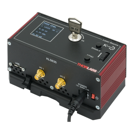
The Menu and Enable buttons allow the various operating modes to be selected easily. There is also a key switch and interlock plug fitted to this compact unit for use in laser applications requiring such functionality. Fig. 1.1 K-Cube Laser Source (KLS635) Page 1 Rev C June 2023... -
Page 4: Power Options
*The previous-generation KPS101 power supply is also compatible and can be used to power a single K-Cube Driver. As a further level of convenience when using these controllers, Thorlabs also offers a 3-channel (KCH301) and 6-channel (KCH601) K-Cube Controller Hub. These... -
Page 5: Apt Software Overview
Chapter 1 Overview utilities are built on top of a sophisticated, multi-threaded ActiveX ‘engine’ (called the APT server) which provides all of the necessary APT system software services such as generation of GUI panels, communications handling for multiple USB units, and logging of all system activity to assist in hardware trouble shooting. - Page 6 KLS Series K-Cube Laser Source All basic operating parameters can be altered and, similarly, all operations (such as setting the scan circle size) can be initiated. Settings and parameter changes can be saved and loaded to allow multiple operating configurations to be created and easily applied.
- Page 7 Chapter 1 Overview Use of the APT Config utility is covered in the PC tutorial (Chapter 5) and in the APTConfig online help file, accessed via the F1 key when using the APTConfig utility. 1.3.3 APT Server (ActiveX Controls) ActiveX Controls are re-usable compiled software components that supply both a graphical user interface and a programmable interface.
- Page 8 Refer to the main APT Software online help file, for a complete programmers guide and reference material on using the Controls collection. This is available either by pressing the F1 key when running the APT server, or via the Start menu, Start\Programs\Thorlabs\APT\APT Help. 1.3.4 Software Upgrades Page 6...
- Page 9 Chapter 1 Overview Thorlabs operate a policy of continuous product development and may issue software upgrades as necessary. The latest software can be downloaded from the ‘services’ section of www.thorlabs.com. Page 7 Rev C June 2023...
-
Page 10: Chapter 2 Safety
KLS Series K-Cube Laser Source Chapter 2 Safety 2.1 Safety Information For the continuing safety of the operators of this equipment, and the protection of the equipment itself, the operator should take note of the Warnings, Cautions and Notes throughout this handbook and, where visible, on the product itself. The following safety symbols may be used throughout the handbook and on the equipment itself. -
Page 11: Warnings Relating To Laser Safety
To prevent injury, all personnel in the vicinity of the laser source should wear appropriate eye protection. 2.4 Laser Markings The KLS1550 is a Class 1 laser product. The KLS635 is a Class 3B laser product. The units are marked as follows:: KLS1550... -
Page 12: Chapter 3 Getting Started
If you experience any problems when installing software, contact Thorlabs on +44 (0)1353 654440 and ask for Technical Support. DO NOT CONNECT THE CONTROLLER TO YOUR PC YET 1) Go to Services/Downloads at www.thorlabs.com and download the software. -
Page 13: Mechanical Installation
(KCH301 and KCH601) are also available - see Section 1.2. for further details. Full instructions on the fitting and use of the controller hub are contained in the handbook available at www.thorlabs.com. Caution When siting the unit, it should be positioned so as not to impede the operation of the control panel buttons. - Page 14 KLS Series K-Cube Laser Source 3.2.3 Using the Baseplate The baseplate must be bolted to the worksurface before the K-Cube is fitted, as shown below. The K-cube is then located on two dowels in the baseplate and secured by four clips. Fig.
-
Page 15: Electrical Installation
This input can be driven from a 0 to 10V voltage source. The input impedence is 16k. Note Thorlabs supply a variety of SMA to BNC and SMC to BNC adaptor and extension cables. Please see our catalog, or visit www.Thorlabs.com for further details. 3.3.2 Using the Safety Interlock and Key Switch The K-Cube Laser Source is a class 1 (1550 nm) / class 3B (635 nm) laser device and therefore is not required to have a safety interlock and/or key switch. - Page 16 KLS Series K-Cube Laser Source 3.3.3 Front Panel Warning The unit must be connected only to a DC supply as detailed in Section 3.3. Connection to a supply of a different rating may cause damage to the unit and could result in injury to the operator. KLS1550 I/O 1 I/O 2...
- Page 17 Section 6.2.2. 3.3.4 Supply Voltage and Current Requirements The unit is fitted with a 3.5 mm DC connector. Thorlabs offers a compact, 15V single way power supply (KPS201) for use with a single laser source cube. Alternatively, an external regulated 15V power supply can be used.
-
Page 18: Connect The Hardware
KLS Series K-Cube Laser Source 3.4 Connect The Hardware 1) Perform the mechanical installation as detailed in Section 3.2. 2) Install the Software. Caution During items (3) to (6) the instructions should be followed in the order stated. Problems may occur if the process is not performed in the correct sequence. 3) Connect the laser source unit to your PC. - Page 19 T h o r l a b s K L S 6 3 5 S w R e v 0 1 0 0 0 1 Fig. 3.4 KLS635 start up screen ® ®...
-
Page 20: Chapter 4 Standalone Operation
KLS Series K-Cube Laser Source Chapter 4 Standalone Operation 4.1 Control Panel Buttons and Indicators Laser Source ENABLE MENU Fig. 4.1 Panel Controls and Indicators Wheel - Used to set the laser power and to scroll through the setting menu options - see Section 4.2. -
Page 21: Top Panel Wheel Operation
Chapter 4 Standalone Operation 4.1.1 Digital Display - Operating Mode During normal operation, the digital display shows the laser output power in mW and dBm (The dBm mode uses a 1mW reference, i.e. 0dBm = 1mW) and the laser output current in mA. -
Page 22: Settings Menu
KLS Series K-Cube Laser Source 4.3 Settings Menu 4.3.1 Overview P O W E R L E V E L After the power up sequence is complete, the normal L A S E R O N operating screen is displayed. 0 . - Page 23 Chapter 4 Standalone Operation 4.3.2 Menu Option - CONTROL SOURCE P O W E R L E V E L This option is used to select the method of adjusting the laser power; top panel wheel and/or software, software L A S E R O N only, or via a 0 to 10V source connect to the rear panel EXT IN connector.
- Page 24 KLS Series K-Cube Laser Source 4.3.3 Menu Option - BRIGHTNESS P O W E R L E V E L In certain applications, it may be necessary to adjust the brightness of the LCD display. The brightness is set as a L A S E R O N value from 30 (dimmest) to 100 (brightest).
- Page 25 Chapter 4 Standalone Operation 4.3.4 Menu Option - INFORMATION This option is used to display the present settings for wavelength, Max Power, Temperature and Software version number. P O W E R L E V E L L A S E R O N Press the MENU button, then use the wheel to scroll 0 .
-
Page 26: Manual Operation Tutorial
KLS Series K-Cube Laser Source 4.4 Manual Operation Tutorial 1) Connect an optical device to the LASER OUT socket on the rear panel. 2) Make power supply connections as detailed in Section 3.3.3. 3) Turn ON the power supply unit. 4) Fit the INTERLOCK pin - see Section 3.3.2. -
Page 27: Chapter 5 Pc Operation - Tutorial
3) Fit the INTERLOCK jack plug - see Section 3.3.2. 4) Turn the Key Switch ON. 5) Run the APT User program - Start/All Programs/Thorlabs/APT User/APT User. The APT server registers automatically the units connected on the USB bus and displays the associated GUI panels as shown in Fig. - Page 28 KLS Series K-Cube Laser Source 6) Click the ‘Enable’ button on the GUI to turn ON the laser output. Notice how the LED in the button is lit to indicate that the laser output is ON.. Fig. 5.1 Gui panel showing jog and ident buttons 7) Click the ‘Ident’...
-
Page 29: Creating A Simulated Configuration Using Apt Config
To create a simulated configuration proceed as follows: 1) Run the APT Config utility - Start/All Programs/Thorlabs/APT/APT Config. 2) Click the 'Simulator Configuration' tab. Fig. 5.2 APT Configuration Utility - Simulator Configuration Tab 3) Enter a configuration name, e.g. - Page 30 KLS Series K-Cube Laser Source 4) In the 'Simulator' field, check the ‘Enable Simulator Mode’ box. The name of the most recently used configuration file is displayed in the 'Current Configuration' window. 5) In the ‘Control Unit’ field, select ‘Laser Source K-Cube (KLS101)’. Page 28 ETN039196-D02...
- Page 31 6) Enter a 6 digit serial number. Note Each physical APT hardware unit is factory programmed with a unique 8 digit serial number. In order to simulate a set of ‘real’ hardware the Config utility allows an 8 digit serial number to be associated with each simulated unit. It is good practice when creating simulated configurations for software development purposes to use the same serial numbers as any real hardware units that will be used.
-
Page 32: Chapter 6 Software Reference
KLS Series K-Cube Laser Source Chapter 6 Software Reference 6.1 GUI Panel The following screen shot shows the graphical user interface (GUI) displayed when accessing the controller using the APT software. Fig. 6.1 Laser Source Software GUI Note The serial number of the unit associated with the GUI panel is displayed in the top right hand corner. -
Page 33: Settings Panel
Enable Button - turns the output of the laser ON and OFF. Note The laser output cannot be enabled unless the interlock jackplug is fitted and the key switch is turned on. Settings display - shows the name of the associated K-Cube together with the following user specified settings: Wavelength - the wavelength of the laser output Max Laser Current - the maximum current limit of the laser source. - Page 34 KLS Series K-Cube Laser Source 6.2.1 Control Tab Fig. 6.1 Laser Source Settings Tab Power Control Source - the source(s) which control the output from the laser unit: If Software Only is selected, the unit responds only to software commands and the output to the laser is that set using the controls on the GUI panel (or software messages if applicable).
- Page 35 to hardware, check the ‘Persist Settings to the Device’ checkbox before clicking the ‘OK button. Caution The ‘Persist Settings’ functionality is provided to simplify use of the unit in the absence of a PC. When the unit is connected to a PC and is operated via APT, the default APTServer settings will be loaded at boot up, even if the ‘Persist Settings’...
- Page 36 I/O 1 and I/O 2 Modes When configured as an input, the IO ports can be used as a general purpose digital input, or for triggering a choice of actions as follows: Disabled - The trigger IO is disabled. Dig IN: Gen. Logic I/P - General purpose logic input (read through status bits using the software messages - see the helpfile for more details).
-
Page 37: Appendix A Preventive Maintenance
The fascia may be cleaned with a soft cloth, lightly dampened with water or a mild detergent. The fibre tip at the Laser Aperture may be cleaned using Thorlabs product FBC1 - One-Step Fiber Bulkhead and Connector Cleaner. Rev C June 2023... -
Page 38: Appendix B Specifications And Associated Parts
USB 3.0 USB Connection Speed USB 1.1 Full Speed (12 Mbps) Weight KLS635 350 g (12.35 oz) KLS1550 300g (10.58 oz) Measured at 20 °C When the EXT IN is used for modulation the KLS works in hybrid constant current mode. -
Page 39: Appendix C Regulatory
Chapter 6 Software Reference Appendix C Regulatory C.1 Declarations Of Conformity C.1.1 For Customers in Europe See Section C.2. C.1.2 For Customers In The USA This equipment has been tested and found to comply with the limits for a Class A digital device, pursuant to part 15 of the FCC rules. - Page 40 KLS Series K-Cube Laser Source C.2 CE Certificate Page 38 ETN039196-D02...
-
Page 41: Appendix D Thorlabs Worldwide Contacts
Waste treatment is your own responsibility. "End of life" units must be returned to Thorlabs or handed to a company specializing in waste recovery. Do not dispose of the unit in a litter bin or at a public waste disposal site.
Need help?
Do you have a question about the KLS635 and is the answer not in the manual?
Questions and answers