Table of Contents
Advertisement
Quick Links
Advertisement
Table of Contents

Related Manuals for Lütze 716455

Summary of Contents for Lütze 716455
- Page 1 Operating Instructions I/O Link Gateway Part No. 716455 Version 01...
- Page 2 Lütze Transportation GmbH Bruckwiesenstraße 17-19 D-71384 Weinstadt Tel.: +49 (0) 7151 6053-545 Fax: +49 (0) 7151 6053-6545 Sales.Transportation@luetze.de www.luetze-transportation.de...
-
Page 3: Table Of Contents
▪ I/O Link Gateway Table of Contents Table of Contents Introduction....................... 6 General information..................8 Symbol description ........................8 2.1.1 Safety messages ......................... 8 2.1.2 Handling notes..........................8 Copyright ............................. 8 Disclaim of liability ........................9 Standards and regulations......................9 Validity of the Operating instructions.................. - Page 4 ▪ I/O Link Gateway Table of Contents 9.2.2 Version 2: I/O Link Gateway with Power Rail ................34 LED displays at the I/O Link Gateway ..................36 Reset button on the I/O Link Gateway..................37 Commissioning of Software ................38 10.1 Download LOCC Pads.......................
- Page 5 I/O Link Gateway The company Friedrich Lütze GmbH reserves the right to make changes to its products in the interest of further technical development. These changes are not necessarily documented in each individual case. These operating instructions are an integral part of the device and contain important information on safety and operation.
-
Page 6: Introduction
▪ I/O Link Gateway Introduction Introduction These operating instructions are part of the LOCC-Box I/O Link Gateway (hereafter referred to as I/O Link Gateway). The operating instructions contain essential information on the safety and operation of the device. Read the operating instructions before using the device in order to exclude possible hazards and to ensure proper use. - Page 7 ▪ I/O Link Gateway Introduction These instructions and further information are available on the website of the Friedrich Lütze GmbH: www.luetze.com Search for the article number, or the product name „I/O Link Gateway...“. Figure: 1: LINK: Data-sheet and Operating Instructions...
-
Page 8: General Information
▪ I/O Link Gateway General information General information Symbol description 2.1.1 Safety messages This document contains safety information, which is characterized by a signal word in combination with a specific colour to indicate the warning level. The information highlights possible dangers and gives instructions on how to avoid them. -
Page 9: Disclaim Of Liability
▪ I/O Link Gateway General information Disclaim of liability This document was written in consideration of the applied standards, regulations and the current state of technology. The content‘s accuracy has been verified. Discrepancies are not excluded. For these discrepancies, we disclaim liability. Applicable changes and additional information will be in the next version of this document. -
Page 10: Validity Of The Operating Instructions
Validity of the Operating instructions These operating instructions apply exclusively to devices with the following part number(s): 716455 - I/O Link Gateway The 6-digit article number of the device can be found in the first number on the name plate. -
Page 11: Related Documents
▪ I/O Link Gateway General information 6. FA number (X)/place of manufacture (YYY)/serial number (Z) 7. Company address / place of manufacture (YYY: "LUT" for Weinstadt and "EQQ" for Czech Republic) 8. Block diagram 9. Company name / web address 10.Approvals / declarations of conformity (e.g., CE marking, UL, etc.) 11.) D bar code with product information Observe the orginally attached information labels, inscriptions, name... -
Page 12: Observe Further Applicable Documents
▪ I/O Link Gateway General information 2.6.2 Observe further applicable documents Be sure to follow all operating instructions for other plant components while using the I/O Link Gateway. Always keep these operating instructions and the applicable documents (e.g., data sheets, instruction leaflets, declarations of conformity, etc.) within easy reach so that they are available when required. -
Page 13: Safety
▪ I/O Link Gateway Safety Safety Safety notes 3.1.1 Content of this operating instructions These operating instructions must have been read and understood prior to installation, use, or servicing the device. Applicable documents Risk of injury and material damage due to non-observance of the applicable documents*, especially the safety instructions in the respective package inserts These operating instructions alone are not sufficient when operating the... -
Page 14: Product Life Cycle
▪ I/O Link Gateway Safety Faultless and safe operation of the product requires proper transport, storage, installation, and assembly as well as careful operation and maintenance The permissible ambient conditions must be observed. These data are specified in the data sheets. Also note the following: Only operate the devices in accordance with this intended use and only in conjunction with the third-party devices and components... -
Page 15: Recipients
▪ I/O Link Gateway Safety Recipients This document addresses planners, project managers, and programmers. It also addresses the operating personnel, who are responsible for the initial operation, the operation and the maintenance of the products and systems. Regarding the personnel, three qualification levels are required. 3.5.1 Operating personnel Risk of injury by deploying insufficiently qualified operating personnel... -
Page 16: Responsibility Of The Operator
▪ I/O Link Gateway Safety and experience so that he can recognize and avoid hazards that may be caused by electricity". In the IEC 60050, it is covered under [IEV 195-4-1]. In the individual sections, reference is made to the qualification level of the personnel. -
Page 17: Electrostatic Discharge (Esd)
▪ I/O Link Gateway Safety Electrostatic Discharge (ESD) Electrostatic discharge can destroy electronic components by generating voltageand energy that are not noticeable to humans. Damage can occur if an electronic component is touched by an electrostatically charged person. Modules will not be immediately recognized as malfunctioning; the malfunction will occur after a longer operating time. -
Page 18: Special Safety Messages
▪ I/O Link Gateway Safety Electric shocks and material damage due to bypassing or bridging protective and safety devices Do not bypass or bridge the protective and safety devices. Overvoltage can cause electric shocks and the devices can be destroyed. 3.10 Special safety messages The I/O Link Gateway and its components correspond to the current state of the... -
Page 19: Additional Safety Notes
▪ I/O Link Gateway Safety Risk of injury from electric current Do not bypass or bridge the protective and safety devices. Overvoltage can cause electric shocks and the devices can be destroyed. Risk of injury and material damage due to non-observance of the operating instructions In any case, read the operating instructions before planning the system in order to avoid or reduce hazards and damage. - Page 20 ▪ I/O Link Gateway Safety The conductor cross-section must be adapted to the set rated current and conform to international and national norms and standards. ATTENTION! The supply cable of the I/O Link Gateway must be suitable for a working temperature range of -25 °C to +50 °C.
-
Page 21: Product Overview
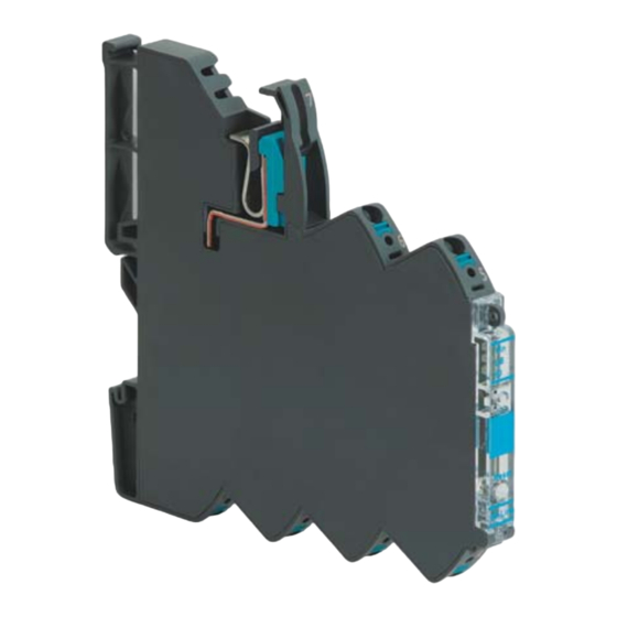
▪ I/O Link Gateway Product overview Product overview Part no. 716455 Description For controlling the I/O Link Gateway. The gateway controls the LOCC-Box Net modules. This enables freely parameterizable operation and current monitoring of the connected LOCC-Box Net modules. - Page 22 ▪ I/O Link Gateway Product overview LED Status display USB interface RESET button Clip-On-Maker You can find further articles and technical information in the online catalog on our website: www.luetze.com.
-
Page 23: Transportation And Storage
▪ I/O Link Gateway Transportation and Storage Transportation and Storage The proper and safe operation of the products requires proper transport, storage, erection, assembly, installation, commissioning, operation and maintenance. Risk of property damage. Risk of damage due to improper handling during transport and storage The device must be protected from moisture, unsafe packaging (mechanical damage), dust, and electrostatic discharge. -
Page 24: Scope Of Delivery
16 "Service” on page 56. The delivery of the I/O Link Gateway includes: I/O Link Gateway Article: 716455 1 × Leaflet I/O Link Gateway documentation ▪ Operating instructions (PDF, Online version) ▪... -
Page 25: Check The Delivery
▪ I/O Link Gateway Scope of Delivery Check the delivery Check the outer packaging for any damage that may have occurred during transport. Unpack the product carefully Observe the ESD regulations when unpacking ▪ Check the package for completeness ▪ Check the individual parts for transport damage Only install and use undamaged products Do not use damaged parts, a function of the device according to specifications... -
Page 26: System Description
However, changes can also be made for the entire LOCC boxes. 7.1.2 Datasheet I/O Link Gateway Datasheet I/O Link Gateway 716455 The current data sheets can also be found at www.luetze.com. There, enter either the product designation:I/O Link Gatewayor the respective part number above in the search field. -
Page 27: Install / Uninstall Hardware
▪ I/O Link Gateway Install / Uninstall Hardware Install / Uninstall Hardware Risk of injury and damage to property due to electric current Affected currents can injure persons and destroy the modules (assemblies). ▪ Disconnect the system from the power supply before mounting and dismounting. -
Page 28: Disassembly Of The I/O Link Gateway
▪ I/O Link Gateway Install / Uninstall Hardware Disassembly of the I/O Link Gateway Assembly variants Installation position: any position Configuration of Parameterization Interface 1. Remove the cov- er of the configu- ration interface on theI/O Link Gateway. 2. Connect to the PC, laptop, or tablet PC by us- ing a USB data... -
Page 29: Wiring
▪ I/O Link Gateway Install / Uninstall Hardware Wiring All connected voltages must meet the requirements for SELV/ PELV. The conductor cross-section must be adapted to the set rated current and conform to international and national standards and regulations. Push-in connection: Stripping length Cable Specification Cross-section... -
Page 30: Pin Assignment
▪ I/O Link Gateway Install / Uninstall Hardware Pin assignment Signal I/O LINK (L-) I/O LINK (C/Q) I/O LINK (L+) COM (LIN) 0V GND DC 24 V... -
Page 31: Commissioning Of Hardware
▪ I/O Link Gateway Commissioning of hardware Commissioning of hardware Risk of injury due to insufficient qualification of the operating personnel Installation, operation, and maintenance must be conducted by electrically skilled personnel. The hardware may only be commissioned by qualified personnel in compliance with the safety regulations. - Page 32 ▪ I/O Link Gateway Commissioning of hardware The module is intended for indoor use and for mounting in control cabinets Observe the ESD regulations. Only use certified components. This is the only way to ensure safe device function. Observe the applicable safety and accident prevention regulations as well as the general rules of technology during setup and operation.
-
Page 33: Commissioning Of The I/O Link Gateway
▪ I/O Link Gateway Commissioning of hardware Commissioning of the I/O Link Gateway LOCC-Box System Setup 9.2.1 Version 1: I/O Link Gateway Blocks diagram: LOCC-Box system with direct feed... -
Page 34: Version 2: I/O Link Gateway With Power Rail
▪ I/O Link Gateway Commissioning of hardware Application example 9.2.2 Version 2: I/O Link Gateway with Power Rail 1. Supply terminal from Set 716425 / 716447 2. Monitoring module LOCC-Box 3. End block from Set 716425 / 716447 4. Copper rail 1 m (716426.xxxx.x) a) Coppeer rail prefabricated (716426.xxxx) 5. - Page 35 ▪ I/O Link Gateway Commissioning of hardware Blockdiagram: LOCC-Box system with power supply set Application example...
-
Page 36: Led Displays At The I/O Link Gateway
▪ I/O Link Gateway Commissioning of hardware LED displays at the I/O Link Gateway Color Status Description green Module is operating green flashing Operating voltag is above- outside the operating range yellow flashing Communication is running GW error LOCC-Box error yellow I/O Link connected flashing... -
Page 37: Reset Button On The I/O Link Gateway
▪ I/O Link Gateway Commissioning of hardware Reset button on the I/O Link Gateway Function Duration [s] Description Restart Restart (reboot) is triggered by pressing the button for at least 5 seconds. Address reset Adress reset is triggered when the button is pressed for more than 10 seconds. -
Page 38: Commissioning Of Software
▪ I/O Link Gateway Commissioning of Software Commissioning of Software 10.1 Download LOCC Pads You can download the software for LOCC Pads, drivers, and corresponding manuals from the following Friedrich Lütze GmbH website: www.luetze.com/de- de/downloads/ The software may only be commissioned by qualified personnel in compliance with the safety regulations. -
Page 39: Parameterization Via Siemens Pct (Port Configuration Tool)
▪ I/O Link Gateway Commissioning of Software 10.4 Parameterization via Siemens PCT (Port Configuration Tool) Here, the parameterization of the control unit LCOS-AB-I of the I/O Link Gateway via the Siemens PCT is shown step by step. With the Port Configuration Tool ("PCT"), STEP7 Engineering has a powerful software for the parameterization of Siemens I/O Link master modules and I/O Link devices. -
Page 40: Function Block Iol_Device
▪ I/O Link Gateway Commissioning of Software Product-specific I/O Link advantages ▪ Low programming effort for I/O link parameterization and diagnostics ▪ Function blocks have a uniform interface for the individual devices ▪ Parameterization and diagnostics during operation ▪ It runs on all CPUs of the SIMATIC S7 ▪... -
Page 41: Lütze I/O Link Gateway (Device Description File)
▪ I/O Link Gateway Commissioning of Software 10.7 Lütze I/O Link Gateway (device description file) Step 1: Import Import the Lütze I/O Link Gateway IODD into SIMATIC S7-PCT 1. Search for LÜTZE-I/O Link Gateway IODD-file in the system. 2. Select the found IODD file. 3. -
Page 42: Offline Mode / Online Mode
▪ I/O Link Gateway Commissioning of Software Step 2: Drag and drop “Drag and drop” the imported IODD file to the already connected slot with the mouse. (1) - (2) 10.8 Offline Mode / Online Mode There are two options for further editing. The offline and the online mode, both are described below. - Page 43 ▪ I/O Link Gateway Commissioning of Software Select connected device at slot 1: [2] I/O Link Gateway 5. The device parameters can be viewed via the "Parameters/Observe/Diagno- sis" tab. Since the device is not connected online, the default parameter val- ues are loaded from the IODD.
-
Page 44: Online Mode
▪ I/O Link Gateway Commissioning of Software 10.10 Online Mode Step 5: Current device parameters... -
Page 45: Possibility Of Automation With Siemens S7 Program Module
▪ I/O Link Gateway Commissioning of Software 10.11 Possibility of automation with Siemens S7 program module You may also operate the I/O Link Gateway by means of Siemens S7 program blocks. This possibility could offer itself as an automated solution. To support the application development, examples for the deployment of Siemens I/O Link call modules are available. -
Page 46: Parameterization Via Iq² Pdct (Port And Device Configuration Tool)
▪ I/O Link Gateway Commissioning of Software 10.12 Parameterization via IQ² PDCT (Port and Device Configuration Tool) Import the IODD Step 1: Follow (1) - (3) Step 2: Establish a connection to the Device... - Page 47 ▪ I/O Link Gateway Commissioning of Software Device connected Step 3: Adapt Device Parameter As soon as the connection from the master to the device is established, the current parameter values are read out and you have the possibility to parameterize the device.
- Page 48 ▪ I/O Link Gateway Commissioning of Software 1. By clicking on the text box, you can select the parameter values you want to change. 2. To transfer your changes to the device, click the "Write" button.
-
Page 49: Firmware Update
▪ I/O Link Gateway Firmware Update Firmware Update 11.1 Introduction Considering the further development of the modules from the LOCC-Box-Net family, updates of the firmware on the gateway are not excluded. 11.2 Download The current software package "LOCC-Pads" is required for the update. This is available as a free download at http://www.luetze.com/downloads/software- interface/. - Page 50 ▪ I/O Link Gateway Firmware Update 3. Navigate to the Extra / Firm- ware Download menu. Enter the password Luetze71384Weinstadt. 4. Confirm with OK. 5. The LOCC-Pads firmware window opens. The currently used version is displayed here. Compare this with the currently downloaded version.
- Page 51 After switching on the supply voltage and connecting with the USB cable, the gateway is recognized as “LOCC-Box-GWIO 716455”. However, the device driver is not installed automatically. In this case, read chapter chapter 8 "Install / Uninstall Hardware” on page 27...
-
Page 52: Operation
▪ I/O Link Gateway Operation Operation Operation must be conducted by at least electrically instructed personnel. Hot surfaces can cause injuries Do not touch the housings during operation or shortly after switching off. Correct and safe operation of the components require proper transport, storage, erection, assembly, installation, commissioning, careful operation, and maintenance. -
Page 53: Hardware Maintenance
▪ I/O Link Gateway Hardware Maintenance Hardware Maintenance The proper and safe operation of the products requires proper and regular maintenance. The components of the I/O Link Gateway are maintenance-free. As a result, ongoing operations don't need to have any inspection or maintenance intervals. -
Page 54: Software Maintenance
▪ I/O Link Gateway Software Maintenance Software Maintenance Incorrectly installed updates can compromise the security of the entire system. Updates must only be installed by authorized personnel. Checks must be conducted by qualified personnel. For general questions about the product or repair requests, please contact the chapter 19 "Service.fm"... -
Page 55: Shutdown And Disposal
▪ I/O Link Gateway Shutdown and disposal Shutdown and disposal Observe the valid environmental regulations of your country for the final shutdown and disposal. Disassemble the device and completely dismantle it before disposal. Dispose of electric parts in line with the regulation for Waste of Electrical and Electronic Equipment (WEEE). -
Page 56: Service
▪ I/O Link Gateway Service Service If you have any further questions regarding the product or our repair service, please contact us at: Friedrich Lütze GmbH Bruckwiesenstraße17-19 71384 Weinstadt Germany Tel.: +49 (0) 7151 6053-0 Fax: +49 (0) 7171 6053-277(-288) E-Mail: info@luetze.de... -
Page 57: Appendix
▪ I/O Link Gateway Appendix Appendix To support application development, these tables are also available in electronic form (e.g., as an Excel file). For more information also see sales help or contact our chapter 16 "Service” on page 56. 17.1 Diagnostic information Via the I/O link master, acyclic "Diagnostic information"... -
Page 58: Cyclic Data
▪ I/O Link Gateway Appendix 17.2 Cyclic data Status channel 1 Status channel Status chan- 00 = Off 1 short circuit nel 1 lwarning 01 = On Current channel 1 PDin 0 = Off 0 = Off 02 = released [xx.xxA] Byte 0 1 = On... -
Page 59: Acyclic Data
Data Type VENDOR_ID 0x0283 IOL_DEVICE_ID 33002 Friedrich Lütze VENDORNAME GmbH VENDORTEXT www.luetze.com PRODUCTNAM LOCC-Box-GWIO PRODUCTID 000000 716455 (Art.No) PRODUCTTEXT I/O Link Gateway 00000000 SERIAL_NUM 0000000000 HW_REVISION Harware Revision FW_REVISION 0.0.0 SW Version Rest and Button value: Assigning the 0x01 node number... - Page 60 ▪ I/O Link Gateway Appendix Index Name Access Default Comment IODD index rights Value Value Data Type Monitoring UInteger LOCC-Box configuration 24 bit with dial Index entry in the IODD 0x01 = Warning UInteger 0x01 = 0x02 = Startup Warning via LED Reset 8 bit...
- Page 61 ▪ I/O Link Gateway Appendix Index Name Access Default Comment IODD index rights Value Value Data Type Index entry in the IODD 0x01 = UInteger Warning 0x01 = Warning 0x02 = Startup via LEDs 8 bit Reset 0x03 = Ignore 0x04 = Failsafe Index entry in the...
- Page 62 ▪ I/O Link Gateway Appendix Index Name Access Default Comment IODD index rights Value Value Data Type UInteger Broadcast Locc-Box Configuration 16 bit UInteger Index entry in the Treshold IODD 8 bit UInteger Index entry in the IODD Characteristic 8 bit UInteger LOCC-Box ID 1 Configuration...
- Page 63 ▪ I/O Link Gateway Appendix Index Name Access Default Comment IODD index rights Value Value Data Type Index entry in the UInteger IODD SW Version 8 bit Index entry in the UInteger IODD Serial number 32 bit UInteger Counter Index entry in the Operating IODD voltage on...
- Page 64 ▪ I/O Link Gateway Appendix Index Name Access Default Comment IODD index rights Value Value Data Type UInteger Characteristic Index entry in the 16 bit setting IODD UInteger Index entry in the SW Version IODD 8 bit Index entry in the UInteger IODD Serial number...
-
Page 65: Explanation Of The Abbreviations Used
▪ I/O Link Gateway Appendix E Appendix E 18.1 Explanation of the abbreviations used Abbreviation Definition Alternating Current, especially according to specifications for alternating voltage Application software (also application program, short application, or application; English application software, short App) Direct Current for direct current; the term is also used for direct voltage Deutsche Gesetzliche Unfallversicherung (German DGUV... - Page 66 ▪ I/O Link Gateway Appendix E (Forts.)Abbreviation Definition Ground – 0 V, 0 potential, mass, The voltage or "potential difference" is measured against this potential. The voltage potential of positive voltages is higher than GND, negative voltages have a voltage potential that is below GND Gateway, a possibility of communication of different networks Top hat rail, German Hutschiene (see TS 35)
- Page 67 ▪ I/O Link Gateway Appendix E (Forts.)Abbreviation Definition EIA-485, also RS-485, is an industry standard for a physical interface for asynchronous serial data RS-485 transmission. The symmetrical line increases the electromagnetic compatibility Receiving line Ambient temperature Tamb Support rail (35 mm) – top hat rail or. „DIN Rail is a mounting rail with a U-shaped profile.
-
Page 68: History Of Changes
▪ I/O Link Gateway History of changes History of changes Version Change Date Newly created 2022-06-23 Document status: Review 2023-04-13 Exchange of drawings 2023-07-14 Technical data are subject to change without notice. Keep for later use. - Page 69 Germany Friedrich Lütze GmbH Postfach 1224 (PLZ 71366) Bruckwiesenstraße 17-19 D-71384 Weinstadt Tel.: +49 (0)7151 60 53-0 Fax: +49 (0)7151 6053-277(-288) info@luetze.de Cable and Cords Austria LÜTZE Elektrotechnische Erzeugnisse Ges.m.b.H. Cable Assembly Niedermoserstraße 18 A-1220 Wien C-Tracks Tel.: +43 (0)1 257 52 52-0 Fax: +43 (0)1 257 52 52-20 Cable fittings office@luetze.at...
Need help?
Do you have a question about the 716455 and is the answer not in the manual?
Questions and answers