Table of Contents
Advertisement
Advertisement
Table of Contents

Related Manuals for Klutch 5793513


Summary of Contents for Klutch 5793513
- Page 1 17" Floor Drill Press Owner’s Manual 227541 WARNING: Read carefully and understand all ASSEMBLY AND OPERATION INSTRUCTIONS before operating. Failure to follow the safety rules and other basic safety precautions may result in serious personal injury. Item #5793513 READ & SAVE THESE INSTRUCTIONS...
- Page 2 Thank you very much for choosing a Klutch product! For future reference, please complete the owner’s record below: Serial Number/Lot Date Code: ________________________________ Purchase Date: ____________________________________________ Save the receipt, warranty, and this manual. It is important that you read the entire manual to become familiar with this product before you begin using it.
-
Page 3: Table Of Contents
Table of Contents Intended Use ............................4 Packaging Contents ..........................4 Technical Specifications ........................4 Important Safety Information ....................... 5 Specific Operation Warnings ....................... 8 Grounding .............................. 9 Extension Cords ..........................10 Main Parts of Product ......................... 11 Assembly Instructions ........................12 Operating Instructions ........................ -
Page 4: Intended Use
Intended Use 17" Floor Drill Press offers 16 speeds, enabling you to choose the best speed for the job. It comes equipped with a quick-release, crank-operated worktable, worklight, X-pattern mounting grooves, depth stop, and adjustable tension spindle return spring--ideal for repetitive drilling of the same depth. . Packaging Contents •... -
Page 5: Important Safety Information
Important Safety Information ⚠WARNING • Read and understand all instructions. Failure to follow all instructions may result in serious injury or property damage. The warnings, cautions, and instructions in this manual cannot cover all possible conditions or • situations that could occur. Exercise common sense and caution when using this tool. Always be aware of the environment and ensure that the tool is used in a safe and responsible manner. - Page 6 ⚠WARNING WORK AREA SAFETY Inspect the work area before each use. Keep work area clean, dry, free of clutter, and well-lit. • Cluttered, wet, or dark work areas can result in injury. Using the product in confined work areas may put you dangerously close to cutting tools and rotating parts. •...
- Page 7 ⚠CAUTION PRODUCT USE AND CARE Do not force the product. Products are safer and do a better job when used in the manner for • which they are designed. Plan your work, and use the correct product for the job. Check for damaged parts before each use.
-
Page 8: Specific Operation Warnings
Specific Operation Warnings ⚠WARNING • Wear eye protection. • Do not wear gloves, necktie, or loose clothing. • Clamp workpiece or brace against column to prevent rotation. Use recommended speed for drill accessory and workpiece material. • • The included chuck key is specially designed to be self-ejecting, reducing the risk of ejecting at high speed. -
Page 9: Grounding
Grounding ⚠WARNING • This machine must be grounded while in use to protect the operator from electrical shock. This unit is equipped with an electrical cord that has an equipment grounding conductor and a grounding plug. The plug MUST be plugged into a matching receptacle that is properly installed and grounded in accordance with ALL local codes and ordinances. -
Page 10: Extension Cords
Extension Cords ⚠WARNING USE A PROPER EXTENSION CORD. Make sure your extension cord is in good condition. When • using an extension cord, be sure to use one heavy enough to carry the current your product will draw. An undersized cord will cause a drop in line voltage, resulting in loss of power and cause overheating. -
Page 11: Main Parts Of Product
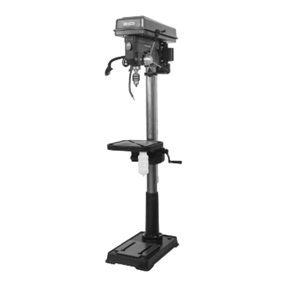
Main Parts of Product Subassembly Pulley Cover Belt Tension lock Knob Belt Tension lever Feed Handle Table Crank Base Column Table Depth Scale locking Screw Pointer Depth Scale Page 11 of 28... -
Page 12: Assembly Instructions
Assembly Instructions ⚠WARNING Turn the power Switch of the tool off and unplug the tool from its electrical outlet before • performing any procedure. Before assembling and using the Drill Press, secure the Base to a supporting structure. • Verify that the intended installation surface has no hidden utility lines before drilling or driving •... - Page 13 6. While holding the Rack and the Table Support as assembled, slide both down onto the Column. Slide the Rack down until the bottom of the Rack is positioned against the Column Support. 7. Replace the Collar onto the Column with its beveled side down, ensuring that the top end of the Rack is engaged in the groove formed between the Collar and the Column.
- Page 14 INSTALLING THE BELTS 1. Undo the Belt Tension Locking Knobs (87) on both sides of the Head. Turn the Belt Tension Lever (97) clockwise to bring the Motor Pulley (109) towards the Spindle Pulley (69), allowing the Belts to be easily slipped over the Pulleys. as shown in Figure D 2.
-
Page 15: Operating Instructions
Operating Instructions ⚠WARNING Turn the Power Switch of the tool off and unplug the tool from its electrical outlet before • performing any procedure in this section. • DO NOT OPERATE WITH ANYGUARD DISABLED, DAMAGED, OR REMOVED. Moving guards must move freely and close instantly. •... - Page 16 CHANGING DRILL SPEED 1. Open the Pulley Cover. 2. Loosen the Belt Tension Lock Knobs on both sides of the Head and turn the Belt Tension Lever clockwise. This will bring the Motor Pulley towards the Spindle Pulley, removing all tension from the drive Belts.
- Page 17 INSTALLING THE BIT CAUTION! Wear heavy-duty work gloves to provide protection when inserting and removing drill bits. Drill bits become very hot during use. Do not remove a drill bit until it has cooled. 1. Loosen the Chuck with the Chuck Key until the jaws of the drill are opened enough to fit the drill bit. 2.
- Page 18 WORKPIECE AND WORK AREA SET UP 1. Designate a work area that is clean and well lit. The work area must not allow access by children or pets to prevent distraction and injury. 2. Route the power cord along a safe route to reach the work area without creating a tripping hazard or exposing the power cord to possible damage.
-
Page 19: Maintenance
Maintenance ⚠WARNING Turn the Power Switch of the tool off and unplug the tool from its electrical outlet before • performing any procedure in this section. Do not use damaged equipment. If abnormal noise or vibration occurs, have the problem •... - Page 20 SPINDLE FEED HANDLES ADJUSTED If the Spindle does not return all the way up or moves up sluggishly, or if it requires too much force to pull down on the Spindle Feed Handles, the amount of spring tension on the Spindle Feed Handles can be adjusted.
-
Page 21: Troubleshooting
Troubleshooting ⚠WARNING Follow all safety precautions whenever diagnosing or servicing the tool • • Disconnect power supply before service. Failure Possible Cause Corrective Action 1. Cord not connected. 1. Check that cord is plugged in. 2. No power at outlet. 2. -
Page 22: Parts Diagram
Parts Diagram Page 22 of 28... -
Page 23: Parts List
Parts List Reference Part Number Part Description Quantity Base Column Support Flat Washer 10 Spring Washer 10 Bolt M10×35 Socket Head Cap Screw M10×10 Column Rack Spindle Feed Handle Bar Spindle Feed Hub Spring Pin 5×30 Spindle Feed Shaft Lock Knob Depth Stop Collar Scale Label Set Screw M6×10... - Page 24 Reference Part Number Part Description Quantity Thin Nut M24×1.5 LED Lamp LED Lamp Power Switch LED Lamp Switch Panel Nut M10x1.5 Oil Pipe Nut M12x1.5 Spring Cap Tension Spring Screw Power Cord Nut M6 Cross-Shape Screw M6×10 Flat Washer 6 Wire Clamp(B) Nut M4 Belt Tension Locking Knob...
-
Page 25: Replacement Parts
Replacement Parts For replacement parts and technical questions, please call Customer Service at 1-800-222-5381. • Not all product components are available for replacement. The illustrations provided are a • convenient reference to the location and position of parts in the assembly sequence. •... -
Page 26: Limited Warranty
Northern Tool and Equipment Company, Inc. ("We'' or "Us'') warrants to the original purchaser only ("You'' or "Your") that the Klutch product purchased will be free from material defects in both materials and workmanship, normal wear and tear excepted, for a period of one year from date of purchase. - Page 27 Page 27 of 28...
- Page 28 Distributed by: Northern Tool & Equipment Company, Inc. Burnsville, Minnesota 55306 www.northerntool.com Made in China Page 28 of 28...
Need help?
Do you have a question about the 5793513 and is the answer not in the manual?
Questions and answers