Table of Contents
Advertisement
Quick Links
Advertisement
Table of Contents
Troubleshooting

Related Manuals for Warmup WWC-09


Summary of Contents for Warmup WWC-09
- Page 1 UFH Wiring Centre WWC-09 Installation manual...
-
Page 3: Table Of Contents
Table of contents Installation summary ������������������������������������������������������������������������������������������� 4 Important information ���������������������������������������������������������������������������������������� 6 Components available from Warmup ��������������������������������������������������������������� 7 Overview ��������������������������������������������������������������������������������������������������������������� 8 Dimensions �������������������������������������������������������������������������������������������������������� 10 Delayed start, zone valve bridge and test switches ��������������������������������������� 11 Step 1 - Location considerations ��������������������������������������������������������������������� 12 Step 2 - Assembly &... -
Page 4: Installation Summary
Installation summary Please read the full installation instructions before proceeding� • Identify a suitable mounting location� Normally above the manifold� • Remove the front cover of the • Drill the pre-marked holes and Wiring Centre and mark the insert a suitable wall plug screw positions on the mounting (if required)�... - Page 5 Installation summary Do not switch on the power supply until all wiring connections have been terminated and front cover re-fitted.
-
Page 6: Important Information
Important information Ensure the Wiring Centre is mounted to a structurally sound wall� Precautions should be taken to reduce the risk of damaging any services within the walls when drilling� Ensure no loose strands wire are left outside of the terminal blocks during wiring�... -
Page 7: Components Available From Warmup
Components available from Warmup Product Code Description Wired controls Warmup UFH Wiring Centre - WWC-09 9 Zone Wiring Centre 6IE-01-OB-DC Warmup 6iE 6IE-01-BP-LC RSW-01-WH-RG (ELM-01-WH-RG) Warmup Element RSW-01-OB-DC (ELM-01-OB-DC) ELT PW (ELT-01-PW-01) Warmup tempo ELT PB (ELT-01-PB-01) Manifold components Warmup S3 Manifold WHS-M-S3-XX XX = No.of ports;... -
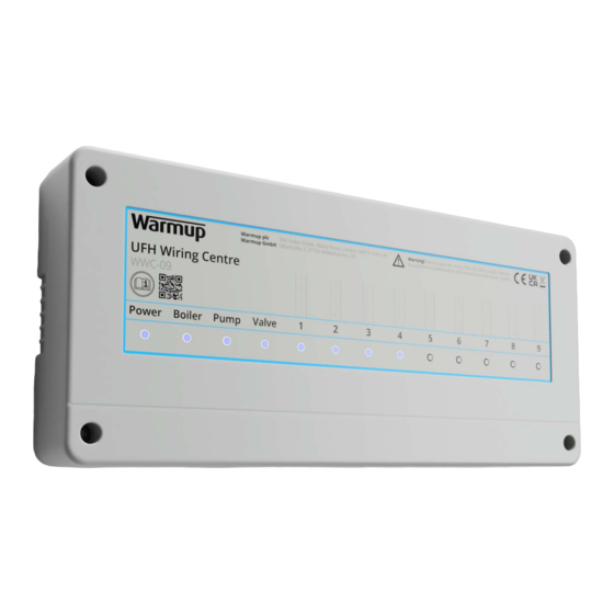
Page 8: Overview
Overview Installation manual QR-Code Links to landing page for country specific manuals Captive case screws x 4 Prevents lost screws 90 second delayed start function Allows time for slow acting actuators to fully open Wall mounting location x 4 Includes 4 wall screws & plugs (+ extra set) LED indicators Shows each output(s) - Page 9 Room name markers Allows each zone to be labelled during installation Reversible cable strain relief clamps x7 Zones 1-9 thermostat / programmer terminals Thermostat connections for underfloor heating / radiators or programmer for hot water Zone 1/2 mode selects Switch between underfloor heating, hot water / radiator Actuator 3-9 terminals...
-
Page 10: Dimensions
Dimensions 50mm 311mm 240mm... -
Page 11: Delayed Start, Zone Valve Bridge And Test Switches
Zone test switches • Warmup actuators are supplied latched open for easy mounting on the manifold� They need to powered on for at least 2 minutes to fully open them and disengage their latches so that they can close the valves�... -
Page 12: Step 1 - Location Considerations
Step 1 - Location considerations Identify a suitable mounting location for Wiring Centre� The location should meet the following requirements; The surface on to which it is to be mounted should be: Mounted where it will not be exposed to temperatures less than 0°C or greater than 45°C�... -
Page 13: Step 2 - Assembly & Mounting
Step 2 - Assembly & mounting The Wiring Centre can be either mounted directly on to a wall or mounted on a DIN rail� It is recommended that walls are assessed prior to drilling to reduce the risk of damaging existing services in the wall� Wall mounting •... -
Page 14: Power Supply
Step 3 - Wiring - Power supply The Wiring Centre requires a 230V AC; 50Hz power supply� The power supply should not be livened until all electrical connections within the Wiring Centre and its interconnected devices have been made and their covers re-fitted. The Wiring Centre and connected devices must be supplied from a single point of isolation�... -
Page 15: Combined Power Supply & Heat Source
Step 3 - Wiring - Combined power supply & heat source Connecting a heat source using a volt-free, 3A Switched e.g. Combi boiler 230V AC; 50Hz Power supply and interlock (5-core HR Flex) = Live = Neutral = Earth Ls = Live supply = Live return (Switched live to heat source) Connecting a heat source using 230V AC;... -
Page 16: Heat Source
Step 3 - Wiring - Heat source The heat source terminals provide a switched power supply� The heating interlock is enabled whenever a demand signal is received� It is recommended that the 90 second delayed start is enabled� This will allow the actuators to open before the heat source is energised�... -
Page 18: Thermostat & Actuators
Step 3 - Wiring - Thermostat & actuators Up to 4 actuators can be connected to a single zone by connecting two into each pair of terminals� Thermostat connection on Wiring Centre Switched live Live Neutral Earth Actuators Live Neutral... - Page 19 Step 3 - Wiring - Thermostat & actuators If a zone requires more than 4 actuators, two or more zones can be bridged together� Thermostat connection on Wiring Centre Earth Switched live & bridge wire Live Neutral Actuators Live Neutral...
-
Page 20: Circulator
Step 3 - Wiring - Circulator The Wiring Centre provides a switched power supply out to a circulator that activates when any underfloor heating channel has demand. If a mixing unit is fitted to the controlled manifold, it should be this secondary circulator that is connected�... -
Page 21: Ufh Zone Valve
Step 3 - Wiring - UFH zone valve Zone valve = Earth = Switched live to Wiring Centre = Live = Switched live to zone valve = Neutral • Where installed on the manifold supply, remove the bridge between Or and Gr� •... -
Page 22: Hot Water
Step 3 - Wiring - Hot water Zones 1 and/or 2 can be used to control hot water circuits by selecting HW/ RAD on the mode switches� In this mode when the programmer and the cylinder thermostat call for heat, the zone valve will be energised� The heat source will be energised when the zone valve end switch closes�... -
Page 23: Radiators
Step 3 - Wiring - Radiators Zones 1 and/or 2 can be used to control conventional radiator circuits by selecting HW/RAD on the mode switches� In this mode when the radiator thermostat calls for heat, the zone valve will be energised� The heat source will be energised when the zone valve end switch closes�... -
Page 24: Wiring Schematic - Typical Installation
Wiring schematic - Typical installation Single Channel Programmer Thermostat Cylinder Thermostat 1.5mm² - 3 Core & Earth 1.5mm² - 2 Core & Earth... - Page 25 Thermostat Thermostat Thermostat...
-
Page 26: Plumbing Schematic - Typical Installation
Plumbing schematic - Typical installation Power IN Legend Heated towel rail Heat source Cylinder thermostat Isolation Valve Hot water cylinder Circulator 3A Switched Fuse Spur Hot water programmer Underfloor heating Motorised zone valve... - Page 27 704 Tudor Estate, Abbey Road, London, NW10 7UW, UK Warning! Device operates using 230V AC; 50Hz supply. Before Warmup GmbH Ottostraße 3, 27793 Wildeshausen, DE installation or maintenance, disconnect from the power supply. UFH Wiring centre (WWC-09) UFH Wiring Centre WWC-09 Power Boiler Pump...
-
Page 28: Troubleshooting
Wiring Centre� across terminals Recheck all wiring L & N of the Wiring Centre? connections� Has the internal fuse Contact on the Wiring Centre Warmup failed? Test all connections for wiring shorts� Replace the F 2A L fuse�... - Page 29 Wiring Centre from manual and correct the the thermostat cable wiring connections� Is there 230V across the L & N terminals of Contact Warmup the zone on the Wiring Centre? Conduct an insulation resistance and continuity Replace cable test on the thermostat cable�...
- Page 30 Set the thermostat to call for heat Is 230 V present across terminals SL & N of the Zone? Check the wiring connections Contact Warmup at the thermostat� Possible thermostat fault� Refer to thermostat manual�...
- Page 31 Check the wiring connections at the thermostat� Possible thermostat fault� Refer to thermostat manual� Are all of the zone test switches are set to Normal operation (No) Switch zone test switch(s) to “No” Contact Warmup...
- Page 32 Does the Zone LED actuator terminals? activate when the test switch is set to test? If the actuator(s) do not open after 2 mins, Check wiring between then they are likely thermostat and faulty Wiring Centre� See issue 3. Contact Warmup...
- Page 33 Ensure issues 1-5 have been ruled out first Is this issue limited to when either zone 1 and/or zone 2 are active? Contact Warmup Is the affected Zone being Set the mode switch used for either HW/RAD? for that zone to UFH...
- Page 34 Only zone valves with end RAD zone valve have an switches are compatible� end switch Please replace� Disconnect the Or and Gr Zone valve is faulty� wires� Is there continuity Please replace� across them when the zone valve is active? Contact Warmup...
-
Page 35: Performance Troubleshooting
Performance troubleshooting ISSUE 1 - The Wiring Centre fuse blows as soon it activates SOLUTION 1 Check all wiring is connected correctly 2 Check the power supply to ensure there are no short circuits across any of the terminals 3 Ensure a F 2A L 250VAC fuse is fitted 4 Check all thermostat connections for short circuits ISSUE 2 - The Wiring Centre fuse blows as soon as any zone activates SOLUTION... -
Page 36: Technical Specifications
Technical specifications UFH Wiring Centre (WWC-09) Operating voltage 230V AC; 50Hz Max. total load 2A resistive Supply overload protection (Use external 3A MCB’s, RCBO’s or fuses for this purpose) Fuse F 2A L 250V 5x20mm Classification of control according Class I to protection against electric shock No. - Page 37 311mm 50mm Warmup plc 704 Tudor Estate, Abbey Road, London, NW10 7UW, UK Warning! Device operates using 230V AC; 50Hz supply. Before Warmup GmbH Ottostraße 3, 27793 Wildeshausen, DE installation or maintenance, disconnect from the power supply. UFH Wiring Centre...
-
Page 38: Warranty
This warranty does not cover removal or re-installation costs and shall not apply if it is shown by Warmup that the defect or malfunction was caused by failure to follow the instruction manuals, incorrect installation or damage which occurred while the product was in the possession of a consumer�... - Page 40 F: 0345 345 2299 Please scan the QR code to provide feedback on your installation The WARMUP word and associated logos are trade marks� © Warmup Plc� 2024 – Regd�™ Nos� 1257724, 4409934, 4409926, 5265707� E & OE� Warmup plc 704 Tudor Estate...
Need help?
Do you have a question about the WWC-09 and is the answer not in the manual?
Questions and answers