Table of Contents
Advertisement
Quick Links
Advertisement
Table of Contents

Related Manuals for Topdon PulseQ AC Mini


Summary of Contents for Topdon PulseQ AC Mini
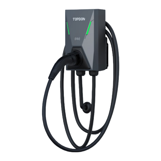
- Page 1 AC Mini AC EV Charger User Manual...
-
Page 3: Table Of Contents
CONTENTS Section 1 - Precautions ............... 4 Section 2 - Standards Compliance ............... Section 3 - What's in the Box ............... Section 4 - Product Overview ............... 12 Section 5 - Installation ............... 20 Section 6 - How to Charge an EV ............... Section 7 - Fault Handling ............... -
Page 4: Section 1 - Precautions
Follow the instructions below closely. Read all the instructions before using this product. This manual contains important instructions for the PulseQ AC Mini charger which shall be followed during the installation, operation, and maintenance of the charger. - Page 5 WARNING A certified AC Surge Protection Device (SPD) is suggested to be installed upstream close to the charging station. SPDs shall comply with standard IEC / EN 61643-11, and the rated voltage against lightning overvoltage shall be up to 2.5kV. A certified Type A or Type B Residual Current Device (RCD) must be installed upstream, close to the EV charger.
- Page 6 1.2 SAFETY NOTES 1.2.1 Safety Signs Used The following types of signs are used in this manual and on the charger. They must be adhered to. CAUTION: Electrical hazard. This indicates severe personal injury or substantial property damage can result if the device is not operated as instructed. ATTENTION: This indicates minor personal injury or material damage can result if the device is not operated as instructed.
- Page 7 1.2.2 Safety Precautions for Installation The following types of signs are used in this manual and on the charger. They must be adhered to. Safety gear (helmet, gloves & protective footwear) must be worn when installing the EV charger. Installation of the product must be performed by a licensed professional.
-
Page 8: Section 2 - Standards Compliance
Conforms to IEC 61851-1: 2017, IEC 62196-2 2.2 Charging Mode and Connection In accordance with IEC 61851-1, the charging mode of PulseQ AC Mini is classified as Mode 3, and the charging connection is a Case C (for models that come with a... - Page 9 Mode 3: A method for the connection of an EV to an AC EV supply equipment permanently connected to an AC supply network, with a control pilot function that extends from the AC EV supply equipment to the Electric Vehicle. Case C: The connection of an EV to a supply network utilizing a cable and vehicle connector (charging plug) permanently attached to the EV...
- Page 10 For models that come with a charging cable: The charging plug of PulseQ AC Mini meets IEC 62196-2, Type 2. The PulseQ AC Mini provides a Type 2 female plug with a charging cable, which only charges EVs with a Type 2 charging socket (vehicle inlet).
-
Page 11: Section 3 - What's In The Box
Section 3 - What's in the Box AC EV Charger Wall-Mounting Accessories User Manual Quick User Guide Quality Certificate Wall Installation Template M5×40mm Expansion Bolt Charging Card Hex Screwdriver User Manual... -
Page 12: Section 4 - Product Overview
Section 4 - Product Overview 4.1 Naming Conventions 4.1.1 Model Names The PulseQ AC Mini is available in five models, each adhering to our standardized naming conventions. See below for more details. PulseQ AC Mini PulseQ AC Mini PulseQ AC Mini... - Page 13 4.1.2 Abbreviations The five PulseQ AC Mini models are categorized into two groups: models that include a charging cable and models that include a charging socket. For ease of reference, the models with a charging cable will be referred to as "Cable Version"...
- Page 14 For PulseQ AC Mini_7K_C5S_EU and PulseQ AC Mini_7K_C7S_EU: (With a charging plug holder) Charging Status Indicator Card Read Area Wall Charging Bracket Plug Holder Charging Plug Power Input Charging Cable Hole Cable Charging Cable Note: The illustrative images in this user manual all depict the cable version model that includes a charging plug holder.
- Page 15 For Pulse Q AC Mini_7K_C5_EU and Pulse Q AC Mini_7K_C7_EU: (Without a charging plug holder) Charging Status Indicator Card Read Area Wall Bracket Power Input Charging Cable Hole Charging Cable Plug Charging Cable...
- Page 16 4.2.2 Socket Version Models For PulseQ AC Mini_7K_S_EU: Charging Status Indicator Card Read Area Wall Bracket Charging Socket Power Input Cable Hole...
- Page 17 Fault (for more details, please see Section 7 - Green & Red blink, 1~11 red Fault Handling) blinks) 4.2 Specifications 4.2.1 Electrical Specifications Product Name PulseQ AC Mini Rated Voltage 230Vac±10%, 50Hz Rated Current 32A 1-Phase Rated Power Charging Interface IEC 62196-2, Type 2 plug...
- Page 18 4.2.2 Functional Descriptions Charging Mode Mode 3 Charging Control Plug and play RFID reader mode Indicator Lights Charging status indicator Safety Protection Surge protection, over temperature, over / under voltage, over current, LN reverse polarity, leakage, ground protection RCD Built-in IΔdc=6mA SCCR 1000A...
- Page 19 4.2.4 Ambient Conditions Working Altitude ≤ 2000m Storage Temperature -40°C ~ +80°C Operating Temperature -30°C ~ +50°C Relative Humidity ≤ 95% RH, no water droplet condensation Vibration <0.5 G, no acute vibration and impact Installation Location Can be installed indoor or outdoors. Should be installed in an area with good ventilation, and not near flammable or explosive gases.
-
Page 20: Section 5 - Installation
Section 5 - Installation 5.1 Pre-installation Inspection When unpacking, please carefully check the following: Whether the accessories are missing according to the packing list. Whether there is any damage to the product that occurred during transportation. Whether the model and specification of the machine's nameplate are consistent with the order requirements. - Page 21 In order to ensure the long-term stable operation of the product, it is recommended not to install the charger in extreme weather, as low or high ambient temperatures may affect the installation effect due to expansions and contractions from temperature changes. Space requirement: When the charger is fixed on the wall, the minimum space requirements are shown in Fig.
- Page 22 5.3 Tools for Installation Please have the following tools prepared before installation. Tool Name Schematic Picture Main Uses Checking the electrical Multimeter connection and measuring the voltage Electric impact Drilling mounting holes in the drill wall Wrench Fastening bolts Diagonal pliers Cutting cables...
- Page 23 Wire stripper Peeling cables Crimping Pressing cable terminal pliers Phillips Fastening screws screwdriver Fastening screws screwdriver (included) Torque Fastening screws to a specified screwdriver torque...
- Page 24 Level tool Ensuring a level installation Measuring distance Tape measure Pencil Marking mounting holes Hammer Driving expansion anchors into the mounting holes...
- Page 25 5.4 Hardwire Installation WARNING: In areas with frequent thunderstorms, add surge protection at the service panel for all circuits. Ensure all power and ground connections, especially those at the breaker and bus bar, are clean and tight. Remove all oxide from all conductors and terminals before connecting any wiring.
- Page 26 Note: The two thumb screws can remain attached to the charger while removing the wall bracket. 2. Use a Phillips screwdriver to unscrew all the 10 screws on the back cover, and then remove the front cover. (See Fig. 5-3) Fig.
- Page 27 Fig. 5-4 4. Use a wire stripper to remove 10~12 mm of insulation from the prepared power wires, and crimp the exposed wire conductors with crimping pliers. (See Fig. 5-5) 10-12mm Fig. 5-5...
- Page 28 Note: Wire ferrules are needed (not included). 5. Remove the wire holding plate on the left. Pass the crimped power cable through the gland, and then thread it through the bottom left hole. (See Fig. 5-6) Fig. 5-6 The supported diameter of outer cable sheath ranges from 17 to 22 mm, and the minimum size of each wire is 6mm².
- Page 29 6. Loosen the three terminal screws with a Phillips screwdriver and fully insert each wire connector into the correct terminal block. Use a torque screwdriver to tighten the terminal screws with a torque of 19.6 N.cm. Then reinstall the wire holding plate.
- Page 30 7. Reinstall the gland and the front cover. (See Fig. 5-8) Fig. 5-8...
- Page 31 5.5 Wall Bracket Installation Before installation, ensure the homeowner has chosen an installation location that allows the charging cable to reach the car's inlet socket while still providing slack. 1. Refer to Fig. 5-9 to understand the dimensions of the wall bracket. Make sure the space on the wall is at least 3.90'' x 2.87'' (99mm x 73mm).
- Page 32 2. Mark the mounting holes on the wall with the installation template. (See Fig. 5-10) Fig. 5-10 3. Drill the mounting holes into the wall with an M6 ~ M10 drill bit at a depth of at least 1.57" (40 mm). (See Fig. 5-11) Fig.
- Page 33 4. Hammer the four plastic expansion anchors into the holes. (See Fig. 5-12) 1.57" Fig. 5-12 5. Fix the bracket to the wall with the four expansion screws (see Fig. 5-13) included in the package. Fig. 5-13...
- Page 34 6. Attach the charger to the wall bracket by passing the two thumb screws through the corresponding holes. (See Fig. 5-14) Fig. 5-14...
- Page 35 7. Install back the hexagon socket head screw to fix the charger to the wall bracket. (See Fig. 5-15) Fig. 5-15...
-
Page 36: Section 6 - How To Charge An Ev
Section 6 - How to Charge an EV 6.1 Charging With a Cable Version Model The PulseQ AC Mini EV charger provides two charging modes for Cable Version models: "Plug and Play" and "RFID Reader" modes. Plug and Play When in the Plug and Play mode, charging starts once the charging is connected. - Page 37 RFID Reader Mode When in the RFID Reader mode, you need to use the supplied charging card to start and stop the charging process. Step 1 Insert the charging plug into the vehicle inlet. Step 2 Touch the supplied card on the charger to start charging. You will hear a beep sound when charging starts.
- Page 38 6.2 Charging With a Socket Version Model The PulseQ AC Mini EV charger provides two charging modes for Socket Version models: Plug and Play, and RFID Reader modes. Plug and Play When in the Plug and Play mode, charging starts once the charging plug is connected.
- Page 39 RFID Reader Mode When in the RFID Reader mode, you need to use the supplied charging card to control the start / stop of charging. Step 1 Get a Type 2 male to Type 2 female cable (not included) designed for detachable connection (Case B).
-
Page 40: Section 7 - Fault Handling
Section 7 - Fault Handling When a fault occurs, the charging status indicator will alternatively blink green (once) and red (1~11 times), then repeat. Indicator Fault Fault Description Suggestion Status Code 1 red blink E001 LN reverse polarity or Check if the input power cable is ground fault correctly connected or the ground wire is securely connected. - Page 41 8 red blinks E008 RCD fault Contact after-sales service. (Charger components may be damaged and need to be replaced.) 9 red blinks E009 CP signal fault Contact after-sales service. (This may be caused by a faulty OBC or CP circuit fault.) 10 red blinks E010 Metering unit fault...
-
Page 42: Section 8 - Warranty
TOPDON shall not be liable for any incidental or consequential damages arising from the device's use, misuse, or mounting. If there is any conflict between the TOPDON warranty policy and local laws, the local laws shall prevail. This limited warranty is void under the following conditions: •... - Page 44 Manufacturer: TOPDON TECHNOLOGY Co., Ltd. 20/F & 32/F, Qianhai Shimao Tower, No. 3040, Xinghai Avenue, Qianhai Shenzhen-Hong Kong Cooperation Zone, Shenzhen, P.R. China Importer: TOPDON EUROPE SL Regus World Trade Centre, Muelle de Barcelona, edif. Sur, 2ª Planta, Barcelona, Cataluña, 08039, Spain...
Need help?
Do you have a question about the PulseQ AC Mini and is the answer not in the manual?
Questions and answers