Advertisement
Quick Links
Advertisement

Related Manuals for Topdon PulseQ AC Lite


Summary of Contents for Topdon PulseQ AC Lite
- Page 1 AC Lite AC EV Charger User Manual...
-
Page 2: Table Of Contents
CONTENTS Section 1 - Precautions ................4 Section 2 - Standards Compliance ................7 Section 3 - Product Overview & Info ................9 Section 4 - What's in the Box? ................13 Section 5 - Installation ................14 Section 6 - LED Indicators ................ -
Page 3: Section 1 - Precautions
Children should be supervised if they are in the vicinity of the PulseQ AC Lite while the PulseQ AC Lite is in use. Children should not use this device. Do not put any of your or another person's body, clothing, or accessories into the tool's electric vehicle connector. - Page 4 All these protection devices shall be chosen with appropriated technical specification, ie working voltage ≥ charging station working voltage, working current ≥ charging station working current, Ingress Protection (IP) ≥ IP54 or installed inside IP54 protection box for outdoor use. 1.2 SAFETY NOTES 1.2.1 Safety Signs Used The following types of signs are used in this manual and on the charger.
- Page 5 1.2.2 Safety Precautions for Installation Safety gear (helmet, gloves & protective footwear) must be worn when installing the EV charger. Installation must be performed carefully due to the risk of electric shock. The charger must be installed vertically to allow for ventilation. Do not install on surfaces that vibrate or where the device could be at risk of impact.
-
Page 6: Section 2 - Standards Compliance
2.1 Safety Standard(s) Conforms to IEC 61851-1: 2017, IEC 62196-2 2.2 Charging Mode and Connection According to IEC 61851-1, the Charging mode of PulseQ AC Lite is Mode 3, and charging connection is Case C. Mode 3: A method for the connection of an EV to an AC EV supply equipment permanently connected to an AC supply network, with a control pilot function that extends from the AC EV supply equipment to the EV. - Page 7 The charging plug of the PulseQ AC Lite meets IEC 62196-2, Type 2. Fig. 2-2 Schematic Diagram of Type 2 Interface The PulseQ AC Lite provides a Type 2 female plug with charging cable, which only charges EVs with a Type 2 charging socket (vehicle inlet).
-
Page 8: Section 3 - Product Overview & Info
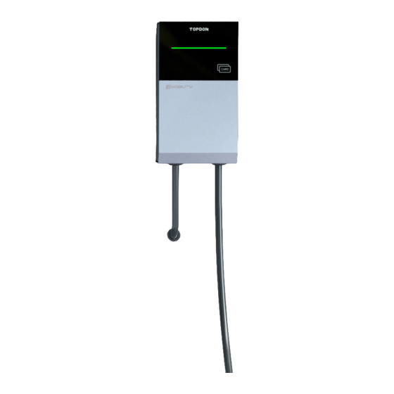
Section 3 - Product Overview & Info 3.1 Shape & Dimensions The shape & dimensions of the PulseQ AC Lite charger are shown in Fig. 3-1 189mm 90mm CARD 340mm Fig. 3-1 Shape & Dimensions of PulseQ AC Lite... - Page 9 3.2 Block Diagram The block diagram of the PulseQ AC Lite charger is shown as Fig. 3-2 RS-485 RFID reader Main CPU Wi-Fi & BT RCMU Charging PT&CT type A+ interface 6mADC Fig. 3-2 Block Diagram It is widely used in various European households for electric vehicle charging, as well as various chargers, parking lots, community garages and public electric vehicle charging areas.
- Page 10 Radio parameters Item Operating Frequency Range Maximum Transmitting power Antenna Gain WIFI 2400-2483.5MHz <18dBm +3dBi Bluetooth 2400-2483.5MHz <2dBm +2dBi Item Operating Frequency Range Transmitting Field Strength Antenna Gain RFID 13.56MHz < 5 dBµA/m @ 3m +0dBi 3.3.2 Functional Descriptions Charging Mode Mode 3 Charging Control Local: Plug and play...
- Page 11 3.3.3 Mechanical Parameters Mounting Wall-mounted Net Weight ≤5.9kg (5m cable), ≤7.1kg (7.5m cable) Dimensions (H×W×D) 340mm × 189mm × 90mm IP Code IP65 IK Code IK10 3.3.4 Ambient Conditions Altitude ≤ 2000m Storage Temperature -40 ~ +80°C Operating Temperature -30 ~ +50°C Relative Humidity ≤...
-
Page 12: Section 4 - What's In The Box
Section 4 - What's in the Box? AC EV Charger Charging Dock Wall-mounting Accessories User Manual Quick User Guide Quality Certificate Wall Installation Template Charging Dock Installation Template M5×40mm Expansion Bolt Charging Card Hex Screwdriver User Manual... -
Page 13: Section 5 - Installation
Section 5 - Installation 5.1 Pre-Installation Inspection When unpacking, please carefully check the following: Whether the accessories are missing according to the packing list. Whether there is any damage to the product that occured during transportation. Whether the model and specification of the machine's nameplate are consistent with the order requirements. - Page 14 200mm (min) 200mm 200mm (min) (min) CARD ≈1200- ≈500- 1300mm 1400mm Fig. 5-1 Minimum Space Requirements for Wall Mounting 5.3 Tools for Installation Please have the following tools prepared before installing Tool Name Schematic Picture Main Uses Checking the electrical connection Multimeter and measuring the voltage Electric impact...
- Page 15 Wrench Fastening bolts Diagonal pliers Cutting cables Wire stripper Peeling cables Crimping pliers Pressing cable terminal Phillips Fastening screws screwdriver Hex screwdriver Fastening screws (included)
- Page 16 Torque Fastening screws to a specified screwdriver torque Level tool Ensuring a level installation Measuring distance Tape measure Pencil Marking mounting holes Hammer Driving expansion anchors into the mounting holes...
- Page 17 5.4 Wall Bracket Installation Before installation, ensure the homeowner has chosen an installation location that allows the charging cable to reach the car's charging port while still providing slack (See Fig. 5-2). CARD Fig. 5-2 WARNING: In areas with frequent thunderstorms, add surge protection at the service panel for all circuits.
- Page 18 2. Mark the mounting holes on the wall with the installation template. (See Fig. 5-4) Fig. 5-4 3. Drill the mounting holes into the wall with a depth of at least 1.57" (40 mm). (See Fig. 5-5) Fig. 5-5...
- Page 19 4. Hammer the plastic expansion anchors into the holes. (See Fig. 5-6) 1.57" Fig. 5-6 5. Fix the bracket to the wall with the expansion screws (See Fig. 5-7) included in the package. Fig. 5-7...
- Page 20 6. Attach the charger to the bracket. (See Fig. 5-8) Fig. 5-8 7. Fix the charger to the bracket with the hexagon socket head screw included in the package, using the provided hex screwdriver. (See Fig. 5-9) Fig. 5-9...
- Page 21 5.5 Hardwire Installation Hardwire installation needs to be done by professional electricians. Please adhere to all safety precautions. 1. Unscrew the two screws on the bottom of the front cover with a Phillips screwdriver, and slide the cover down to remove it. (See Fig. 5-10) Fig.
- Page 22 2. Unscrew the eight screws to remove the inner cover. (See Fig. 5-11) CARD Fig. 5-11 3. Remove the gland at the bottom right of the charger. You can use a large wrench if needed. (See Fig. 5-12) CARD Fig. 5-12...
- Page 23 4. Use a wire stripper to remove 10~12 mm of insulation from the prepared power wires, and crimp the exposed wire conductors with the crimping pliers. (See Fig. 5-13) 10-12mm Fig. 5-13 Note: Wire ferrules are needed (not included). 5. Pass the crimped power cable through the hole. (See Fig. 5-14) CARD Fig.
- Page 24 The supported diameter of outer cable sheath ranges from 17 to 22 mm. For chargers rated at 7kW / 22kW, the minimum size of each wire is 6mm². For chargers rated at 11kW, the minimum size of each wire is 2.5mm². 6.
- Page 25 7. Reinstall the gland and the covers. CARD Fig. 5-16 5.6 Network Cable Installation 1. Remove the protective cap of the network port on the bottom center of the charger. (See Fig. 5-17) Fig. 5-17...
- Page 26 2. Insert the RJ45 plug into the network port. (See Fig. 5-18) Fig. 5-18 5.7 Charging Dock Installation 1. Please make sure the space on the wall is at least 2.93" × 2.28" (74.3mm × 58mm). 58mm Fig. 5-19...
- Page 27 2. Place the installation template on the wall and mark the mounting holes. (See Fig. 5-20) Fig. 5-20 3. Drill the mounting holes on the wall with a depth of at least 1.57" (40 mm), and hammer the plastic expansion anchors into the holes. (See Fig. 5-21) 1.57"...
- Page 28 4. Fit the charging plug socket into the charging dock. (See Fig. 5-22) Fig. 5-22 5. Fix the charging dock on the wall with the expansion screws included in the package. (See Fig. 5-23) Fig. 5-23 Please put the charging plug back to the Charging Dock after each charge.
-
Page 29: Section 6 - Led Indicators
Section 6 - LED Indicators Charging Status Indicator CARD Fig. 6-1 Indicator Name Indicator Status Connotation Color Green Standby Blue Charging plug connected, ready to start charging / Charging complete (plug still connected) Charging Status Indicator Pulsing Charging in progress Green &... -
Page 30: Section 7 - Fault Handling
Section 7 - Fault Handling When a fault occures, the charging status indicator will blink green (once) and blink red (1~12 times), then repeat. Indicator Handling Fault Code Meanings Status Methods 1 red blink E001 LN reverse polarity or Check if the input power cable is ground fault correctly connected or the ground wire is securely connected. -
Page 31: Section 8 - Warranty
TOPDON shall not be liable for any incidental or consequential damages arising from the device's use, misuse, or mounting. If there is any conflict between the TOPDON warranty policy and local laws, the local laws shall prevail. This limited warranty is void under the following conditions: •... - Page 32 Manufacturer: TOPDON TECHNOLOGY Co., Ltd. 20/F & 32/F, Qianhai Shimao Tower, No. 3040, Xinghai Avenue, Qianhai Shenzhen-Hong Kong Cooperation Zone, Shenzhen, P.R. China Importer: TOPDON EUROPE SL Regus World Trade Centre, Muelle de Barcelona, edif. Sur, 2ª Planta, Barcelona, Cataluña,...
Need help?
Do you have a question about the PulseQ AC Lite and is the answer not in the manual?
Questions and answers